4057
Endoluminal imaging with MEMS in series with loop coil for active decoupling1Univ Lyon, INSA-Lyon, Université Claude Bernard Lyon 1, UJM-Saint Etienne, CNRS, Inserm, CREATIS UMR 5220, U1206, F-69100, Lyon, France, 2GE Healthcare, Buc, France, 3GE Healthcare, Aurora, OH, United States
Synopsis
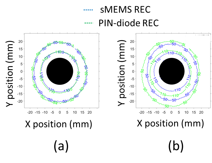
A Receiver-Endoluminal-Coil (REC) integrating an active-decoupling circuit based on MEMS switch in series with the loop (sMEMS) was built and characterized on bench and at 1.5T. The results were compared to a conventional PIN-diode REC. Although the quality factor of sMEMS was significantly lower (34%) than the one of PIN-diode, efficient (|S11|<-0.1dB) and fast (delays<8µs) active-decoupling were obtained for the sMEMS. Obtained MR images display no hyper intensity or artifacts due to active-decoupling failure. SNR-values and SNR-isocontours of sMEMS were similar to those of PIN-diode for GRE and lower for FSE sequences. sMEMS can bring new coil-design possibilities for endoluminal-imaging.
Introduction
Despite the improved Signal-to-Noise Ratio (SNR) of MRI arrays of external receiver-coils1, it is still not possible to depict thin bowel and colon wall. Receiver-Endoluminal-coils (RECs) used close to the region of interest provide a high local SNR2. However, the strong coupling between REC and RF transmitter-coil during RF-transmission leads to a mutual induction and subsequent non-uniform B1 field in the vicinity of the REC-loop; thus RF-receiver-coils must be decoupled3. To ensure this capability, the PIN-diode is the mostly used component in the literature. Another decoupling solution resides in the use of Micro ElectroMechanical System (MEMS) switches4 which can be used also to bring new possibilities for MR-REC designs5. In this work, we propose to characterize a REC-loop using a MEMS switch to fulfill the role of active decoupling and compare its performance to a conventional PIN-diode REC.Methods
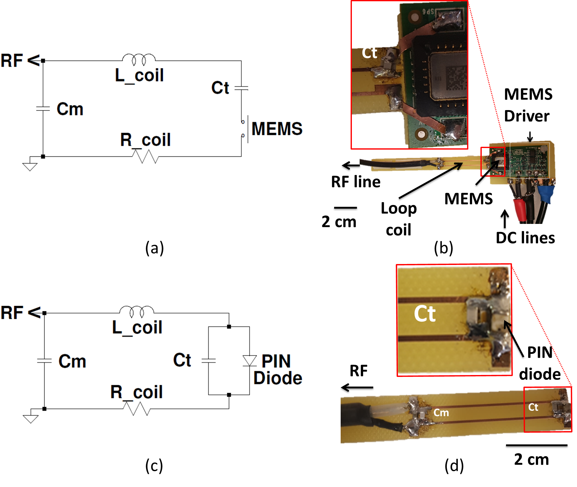
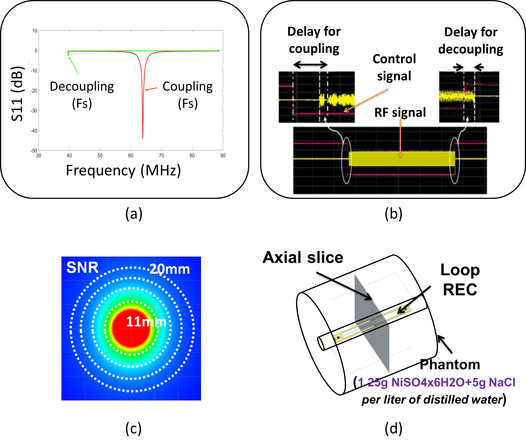
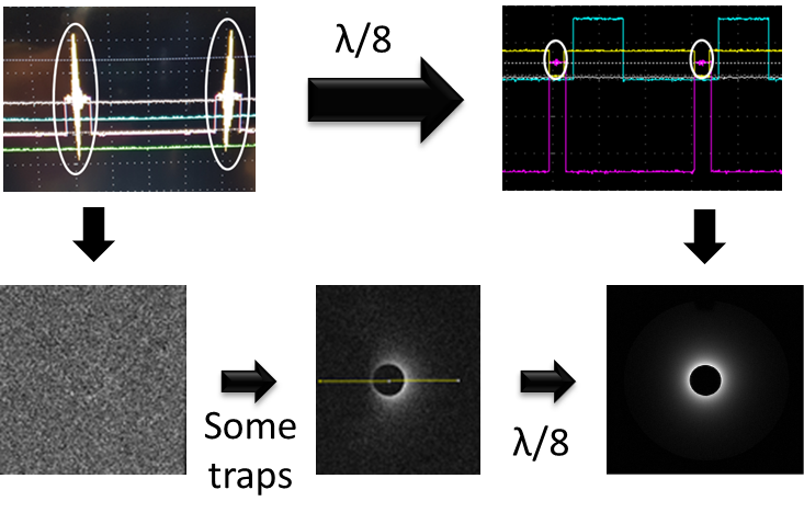
To complete our previous work on MEMS placed in parallel with the loop6, a new set of prototype based on MEMS switch integrated in series (sMEMS) into a rectangular REC-loop (Fig.1-ab) was built and characterized on bench and images of a cylindrical phantom (Fig.2-d) were acquired. Its performance was then compared to a REC with conventional PIN-diode (Fig.1-cd). RECs were tuned to the Larmor frequency (F0) at 1.5T (63.9MHz) and matched to a 50Ω using a network analyzer. As showed in Fig.2, reflection coefficients S11 were measured and coil quality factors (Q-values) were derived at -3dB bandwidth. Decoupling efficacy was assessed at both Larmor and decoupled (Fd) resonance frequencies. Then, switching delays were measured. A circular broadband copper-loop connected to an RF-synthesizer enabled the generation of an RF signal at F0 that was transmitted to the REC by inductive coupling. The detected RF signal was measured using an oscilloscope. A periodic square signal was used as to couple/decouple the REC and delays were measured as the time between the square signal and the RF-signal. MR images were performed at 1.5T MR-scanner using the body-coil for RF transmission. Every REC was connected to the MRI connector (A-plug). A power-supply was used to supply 10V and 82V to the MEMS driver circuit. Connections through the Farday’s cage of the MRI-room was strongly filtered using adjusted custom-made λ/8 Coaxial Cable Traps (CCTs) to avoid induced RF-signal7 which would otherwise lead to not only strong image quality degradation but also damage to the MEMS and/or its driver. MR experiments were performed at 1.5T MR-scanner (MR450w). Multiple axial slices were acquired using gradient echo (GRE) and fast spin echo (FSE) sequences. Acquired images were post-processed. sMEMS and PIN RECs performances were compared in terms of SNR-uniformity distributions and mean-SNR.Results
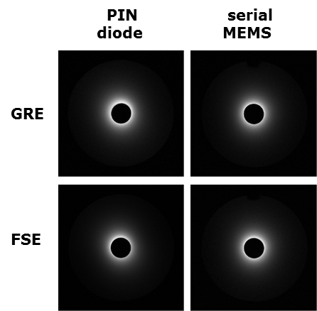
Q-values were equal to 62 and 41 for PIN-diode and sMEMS, respectively. During decoupling phase, S11 at F0 were inferior to -0.3dB. The PIN-diode REC frequency was shifted to 29.3MHz. The sMEMS loop was completely open (no resonance). Switching delays were below 0.7 and 8µs for PIN-diode and sMEMS RECs respectively. In the absence of traps (imaging experiments), RF-signal induced by the body-coil during transmit phase are superimposed to the DC control signal (up to 20V peak-to-peak) which could destroy the driver MEMS. Traps were added to avoid these problems (Fig.3). In the obtained images, no signal saturation or artifacts due to active decoupling failure were observed (Fig.4) for both sMEMS and PIN. SNR-values and elliptical SNR uniformity distributions of sMEMS were similar to those of PIN-diode for GRE sequence but lower for FSE sequence (Fig.5).Discussion
The loaded Q-value of sMEMS was significantly lower (~34%) than the one with PIN-diode. This is mainly due to the location of MEMS and PIN-diode on the coil-loop. In the coupled (receive) state, the MEMS (integrated in series to the REC-loop) is closed and considered as an additional 0.5-1 Ω parasitic resistance in the loop that should be compared to the loop resistance. The MEMS REC switching delays are longer than the PIN REC which can be explained by the time necessary to mechanically move the switch in addition to the switching delays of its driver circuit8. However, controlled MEMS circuit have switching delays inferior to 8µs which are of the same order than controlled PIN-diode (<8µs) with added control circuit)9 and optical-based decoupling circuits (<14µs)10. MEMS active decoupling is still compliant with most MR clinical applications. S11 (~0dB), FS (~29MHz) of PIN-diode and the open loop of sMEMS both demonstrate an efficient active decoupling. This was confirmed on MR images where no signal artifacts were noticed. The similar SNR-values and SNR distributions of sMEMS and PIN-diode obtained with the GRE sequence demonstrates the image performance of sMEMS REC. However, the difference obtained with the FSE sequence is probably due to the strong RF power generated during the FSE acquisition which affects the added equipment (traps, DC coaxial cables) to the sMEMS design and thus increases the noise on the MEMS images.Conclusion
The good performance (efficient and fast active decoupling and sufficient SNR) of sMEMS may offer interesting new designs of coils. sMEMS could be useful in particular when coil reconfiguration is necessary. It could open the way to new industrial designs and clinical endoscopic procedure for applications such as colon cancer.Acknowledgements
Authors would like to thank the LABEX PRIMES of University of Lyon, which has supported this work within the program "Investissements d'Avenir" (ANR-11-IDEX-0007) operated by the French National Research Agency (ANR).References
1. Roemer PB, Edelstein WA, Hayes CE, Souza SP, Mueller OM: The NMR phased array. Magn Reson Med 1990; 16:192–225.
2. Beuf O, Pilleul F, Armenean M, Hadour G, Saint-Jalmes H: In vivo colon wall imaging using endoluminal coils: Feasibility study on rabbits. J Magn Reson Imaging JMRI 2004; 20:90–6.
3. Edelstein WA, Hardy CJ, Mueller OM: Electronic decoupling of surface-coil receivers for NMR imaging and spectroscopy. J Magn Reson 1969 1986; 67:156–161.
4. Spence D, Aimi M: Custom MEMS switch for MR surface coil decoupling. In Proc 23rd Annu Meet ISMRM Tor Can; 2015:0704.
5. Raki H, Tse-Ve-Koon K, Souchay H, Robb F, Lambert S, Beuf O: Design of a reconfigurable endoluminal coil using MEMS switches. In 27th Annu Meet ISMRM. Montréal, Canada; 2019.
6. Raki H, Saniour I, Robb F, et al.: Comparison of single-loop endoluminal receiver coils based on serial or parallel active decoupling circuits using controllable MEMS switches. In Jt Annu Meet ISMRM-ESMRMB 2018. Paris, France; 2018.
7. Schaller BM, Magill AW, Gruetter R: Common modes and cable traps. In Proc Intl Soc Mag Reson Med. Volume 19; 2011:4660.
8. Maunder A, Rao M, Robb F, Wild JM: Comparison of MEMS switches and PIN diodes for switched dual tuned RF coils. Magn Reson Med 2018; 80:1746–1753.
9. Der E, Volotovskyy V, Sun H, Tomanek B, Sharp JC: Design of a high power PIN‐diode controlled switchable RF transmit array for TRASE RF imaging. Concepts Magn Reson Part B Magn Reson Eng 2018; 48B.
10. Saniour I, Aydé R, Perrier AL, et al.: Active optical-based detuning circuit for receiver endoluminal coil. Biomed Phys Eng Express 2017; 3:025002
Figures