4056
Development and Evaluation of a pTx Transceiver Cardiac Array Based on Y-Shape Central 3-Loop Arrangement for Cardiac MRI in Pigs at 7T
Ibrahim A. Elabyad1, M. Terekhov1, D. Lohr1, and Laura M. Schreiber1
1Chair of Cellular and Molecular Imaging, Comprehensive Heart Failure Center (CHFC), University Hospital Wuerzburg, Wuerzburg, Germany
1Chair of Cellular and Molecular Imaging, Comprehensive Heart Failure Center (CHFC), University Hospital Wuerzburg, Wuerzburg, Germany
Synopsis
An 8-element anterior array based on central 3-elements Y-shape arrangement was combined with a rectilinear 8-elements posterior array to form a dedicated 8Tx/16Rx pTx transceiver cardiac array for pigs was developed. The hardware and imaging performance of the pig array was validated through EM-simulations, phantom and ex-vivo MR-measurements at 7T. Combined SNR, FA, g-factor maps, and high-resolution ex-vivo cardiac images were acquired with an in-plane resolution of 0.3mm×0.3mm. A SNR of 36±23 was achieved within the heart of the pig. Parallel imaging with acceleration factor (R=4) was possible while keeping the mean g-factor within the heart region at 1.14.
Introduction
Various RF-coil types and arrays have been introduced for cardiac magnetic resonance imaging (cMRI) in humans at UHF (e.g., microstrip line resonators1, 2, Tx/Rx loop arrays3–6, dipole antenna arrays7–9, and combined dipoles and loop arrays10, 11. However, pigs have quite different thorax shape than humans. The misuse of the human coils for performing cMRI in pigs will lead to a degradation of the SNR and $$$B_1^+$$$-field homogeneity due to less loading and suboptimal element dimensions. For cMRI, it is required to design a densely multi-row, multichannel array with good decoupling mechanism and geometrical loop configurations to enable RF-shimming12, 13 and parallel imaging along all standard and multi-oblique cardiac views. In this work, we report the design, simulation and testing of an 8-element anterior cardiac array combined with a rectilinear 8-element posterior array to form an 8Tx/16Rx dedicated pTx coil array to demonstrate the feasibility of cMRI in pigs at 7T.Methods
The anterior array design was based on central 3-elements (1, 3, and 4) form together Y-shape loops, which were decoupled using a common conductor and three shared decoupling capacitors (SDC) (Fig. 1a). The surrounding 5-elements (2, 5, 6, 7, and 8) were chosen to be triangular in shape. The geometrical 8-loops distribution of anterior array was selected to be symmetric around the central Y-shape 3-elements to enable RF-shimming and parallel imaging along all standard and multi-oblique cardiac views. The anterior array was combined with a standard posterior array comprised of 8-loop elements based on a standard rectilinear design (Fig. 1b) to form an 8Tx/16Rx pTx dedicated pig array. The dimensions of the central Y-shape 3-elements were 4.3cm×7.53cm, 3.5cm×9.0cm, and 3.5cm×9.0cm, respectively. The dimensions of the elements were chosen to achieve a sufficient $$$B_1^+$$$-field penetration at about 10cm depth within the pig torso in order to create a balance between the individual 8-loop dimensions and the external dimensions of the array12. The central Y-shape 3-elements (1, 3, and 4) were decoupled using two SDCs of ($$$C_1^d$$$ and $$$C_2^d$$$). The surrounding five elements 2, 5, 6, 7, and 8 were chosen to be triangular in shape. They are decoupled from the central Y-shape 3-elements using two SDCs of ($$$C_4^d$$$ and $$$C_5^d$$$) and gaps of 1.4cm and 1.2cm. The elements 5 and 7 and the identical mirrored elements 6 and 8 were decoupled using a SDC of ($$$C_3^d$$$). For each loop, two equal tuning capacitors ($$$C_1^t$$$, $$$C_2^t$$$, $$$C_3^t$$$, and $$$C_4^t$$$) were distributed equally in the gaps between the segment in order to have the element resonating at 297.2 MHz. The total external dimension for the anterior array was 19.1cm×23.1cm. The rectilinear posterior array was built using 4×2 rectangular symmetric elements configuration13. EM-simulations were carried out using CST-Microwave-Studio for array design and $$$B_1^+$$$-field optimization in a pig phantom ($$$\epsilon_{r}$$$= 59.0 and $$$\sigma$$$= 0.79S/m) (Fig. 1d). RF-circuit co-simulation was employed for good matching, tuning, and decoupling at 297.2 MHz14. An in-house developed dedicated pig body phantom (volume≈16L) was built to mimic approximately the thorax shape of the pig and to validate the $$$B_1^+$$$-field simulations (Fig. 1e). The dedicated pig array was tested in phantom and 46kg ex-vivo pig with the measurement of FA-maps, SNR-maps, and g-factor maps with high parallel imaging acceleration factors (R=2, 3 and 4). The acceleration was set in the left/right (L/R) direction. The coil array was tested in an ex-vivo experiment with one female 46kg pig (German Landrace, Heinrichs Tierzucht GmbH, Heinsberg, Germany). The animal was provided for an ex-vivo measurement, following its approved use in project 55.2 DMS 2532-2-664 (Regierung Unterfranken, Germany). All measurements were performed on a 7T whole-body 7T Siemens Magnetom Terra scanner (Siemens Healthineers, Erlangen, Germany) in pTx mode.Results and Discussion
Fig. 2 illustrates the simulated central transversal $$$B_1^+$$$-field distribution and the measured FA-maps within the pig body phantom for the individual 8Tx-channels ($$$T_{x1}$$$-$$$T_{x8}$$$). The dedicated pig array generates spatial $$$B_1^+$$$-field distribution appearing for all 8Tx-channels. Good agreement between CST-simulations and MR-measurements was achieved for the 8Tx-channels. Fig. 3 demonstrates the simulated combined central transversal $$$B_1^+$$$-field and the measured FA-map, SNR-map, and g-factor maps within the pig phantom. There were some differences between simulated and measured FA-maps. Parallel imaging with an acceleration factor of R=4 was possible with the pig array to maintain the g-factor within the selected ROI at 1.18±0.12. Fig. 4 shows the noise correlation matrix, SNR-map, FA-map, and g-factor maps acquired using the pig array loaded with an ex-vivo 46kg pig. The measured SNR ± SD within the heart ROI of the pig was 36 ± 23. The dedicated pig array has good parallel imaging performance with R=4. The mean ± SD of the g-factor in the heart ROI was 1.14±0.07. High resolution ex-vivo long axis (LA) and short axis (SA) cardiac images were acquired with an in-plane resolution of up to 0.3mm×0.3mm using the dedicated pig array (Fig. 5).Conclusion
In this work we demonstrated the feasibility of performing cMRI in pigs at 7T using an 8-elements array design based on central 3-elements Y-shape arrangement combined with a rectilinear 8-elements posterior array. The main achievement of the dedicated pig coil array was the possibility to obtain cardiac images with high in-plane resolution of up to 0.3mm×0.3mm.Acknowledgements
This project is funded by the German Ministry of Education and Research (BMBF) with grant # 01EO1004 & 01EO1504.References
- C.J. Snyder et al., Initial results of cardiac imaging at 7 Tesla, Magn. Reson. Med. 61 (3) (2009) 517–524.
- J.T. Vaughan et al., Whole-body imaging at 7T: preliminary results, Magn. Reson. Med. 61 (1) (2009) 244–248.
- A. Graessl et al., Modular 32-channel transceiver coil array for cardiac MRI at 7.0T, Magn. Reson. Med. 72 (1) (2014) 276–290.
- M.A. Dieringer et al., Design and application of a four-channel transmit/receive surface coil for functional cardiac imaging at 7T, J. Magn. Reson. Imag. 33 (3)(2011) 736–741.
- A. Gräßl et al., Design, evaluation and application of an eight channel transmit/receive coil array for cardiac MRI at 7.0T, Eur. J. Radiol. 82 (5) (2013) 752–759.
- C. Thalhammer et al., Two-dimensional sixteen channel transmit/receive coil array for cardiac MRI at 7.0 T: design, evaluation, and application, J. Magn Reson Imag. 36 (4) (2012) 847–857.
- C. Oezerdem et al., 16-channel bow tie antenna transceiver array for cardiac MR at 7.0 tesla, Magn. Reson. Med. 75 (6) (2016) 2553–2565.
- A.J.E. Raaijmakers, P.R. Luijten, C.A. van Den Berg, Dipole antennas for ultrahigh-field body imaging: a comparison with loop coils, NMR Biomed. 29 (9) (2016) 1122–1130.
- M.A. Ertürk et al., Toward imaging the body at 10.5 tesla, Magn. Reson. Med. 77 (1) (2017) 434–443.
- M.A. Ertürk, A.J. Raaijmakers, G. Adriany, K. Ug˘urbil, G.J. Metzger, A 16-channel combined loop-dipole transceiver array for 7 T esla body MRI, Magn. Reson. Med. 77 (2) (2017) 884–894.
- B.R. Steensma et al., An 8-channel Tx/Rx dipole array combined with 16 Rx loops for high-resolution functional cardiac imaging at 7 T, Magn Reson Mater Phy 31 (1) (2018) 7–18.
- I.A. Elabyad et al., Design and evaluation of a novel symmetric multichannel transmit/receive coil array for cardiac MRI in pigs at 7 T, IEEE Trans. Microw. Theory Techn., 67 (9) (2019) 3928–3945.
- I.A. Elabyad et al., Design of a Novel Antisymmetric Coil Array for Parallel Transmit Cardiac MRI in Pigs at 7 T, J. Magn Reson, 305 (2019) 195–208.
- M. Kozlov, R. Turner, Fast MRI coil analysis based on 3-D electromagnetic and RF circuit co-simulation, J. Magn Reson 200 (1) (2009) 147–152.
Figures
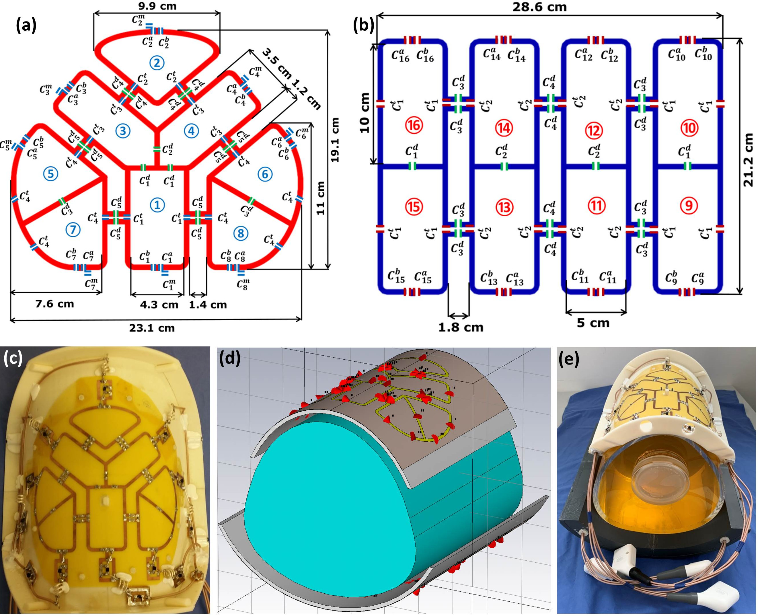
Figure 1 Schematic of
the dedicated anterior cardiac array (a), posterior cardiac
array (b), coil prototype of the anterior
array (c), RF simulation model of the array
loaded with a pig phantom (d), both dedicated
anterior
and posterior cardiac prototypes
for pigs
loaded with an in-house developed pig phantom (e).
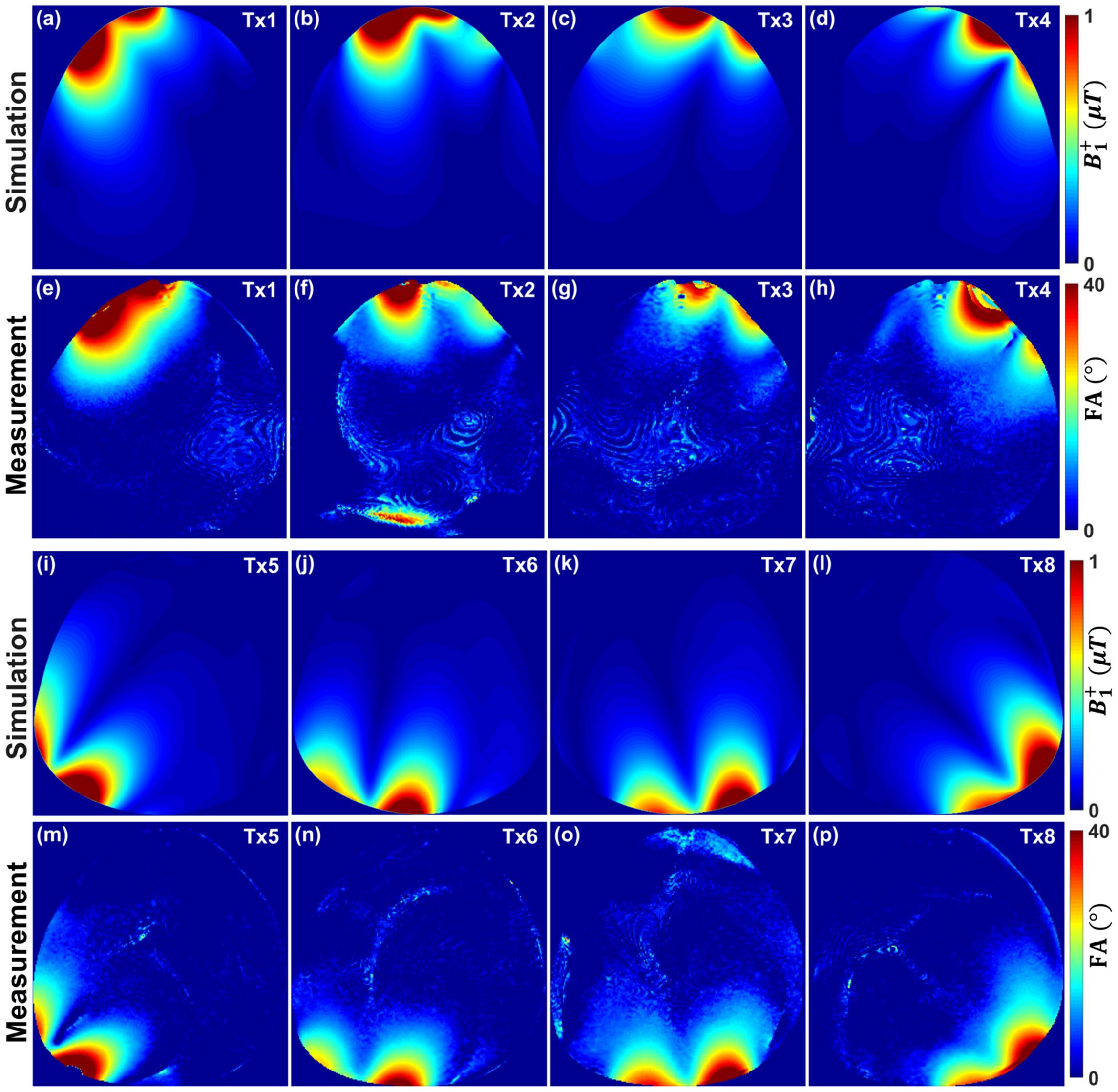
Figure 2 Simulated central transversal B1+ field distribution in μT and the measured FA maps in degrees for the
individual 8Tx channels of the dedicated pig cardiac array within a pig
phantom. Simulation (a)-(d) & (i)-(l). Measurement (e)-(h) & (m)-(p).
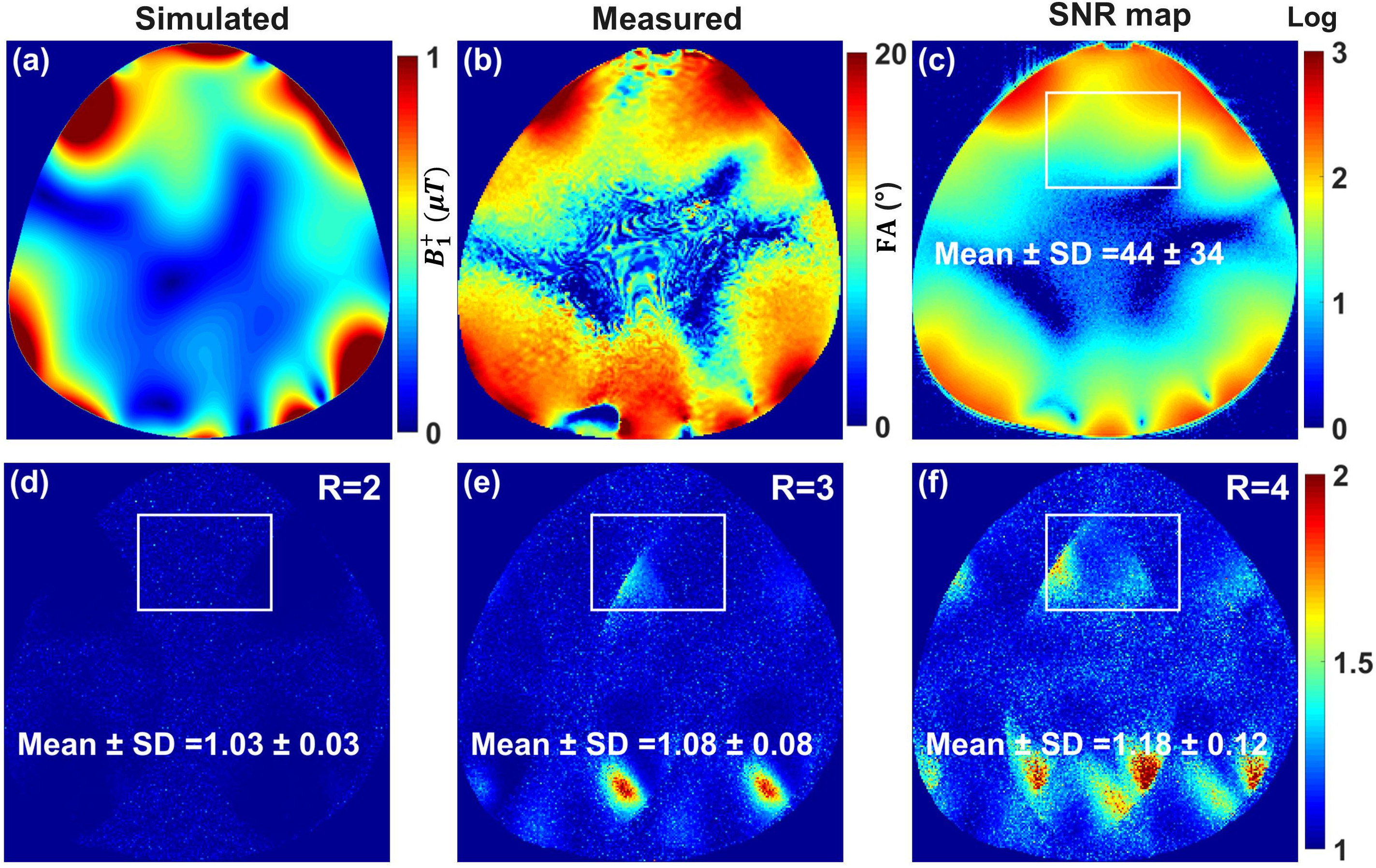
Figure 3 Simulated combined central transversal B1+ field distribution in μT (a) and the
measured FA map in degrees (b), combined SNR
map (c), and g-factor maps of R = 2, 3, 4, and
6 acquired using the dedicated pig cardiac array within a pig phantom with acceleration
in the L/R direction (d)-(f). The mean ± SD of g-factor were computed in the
heart ROI.
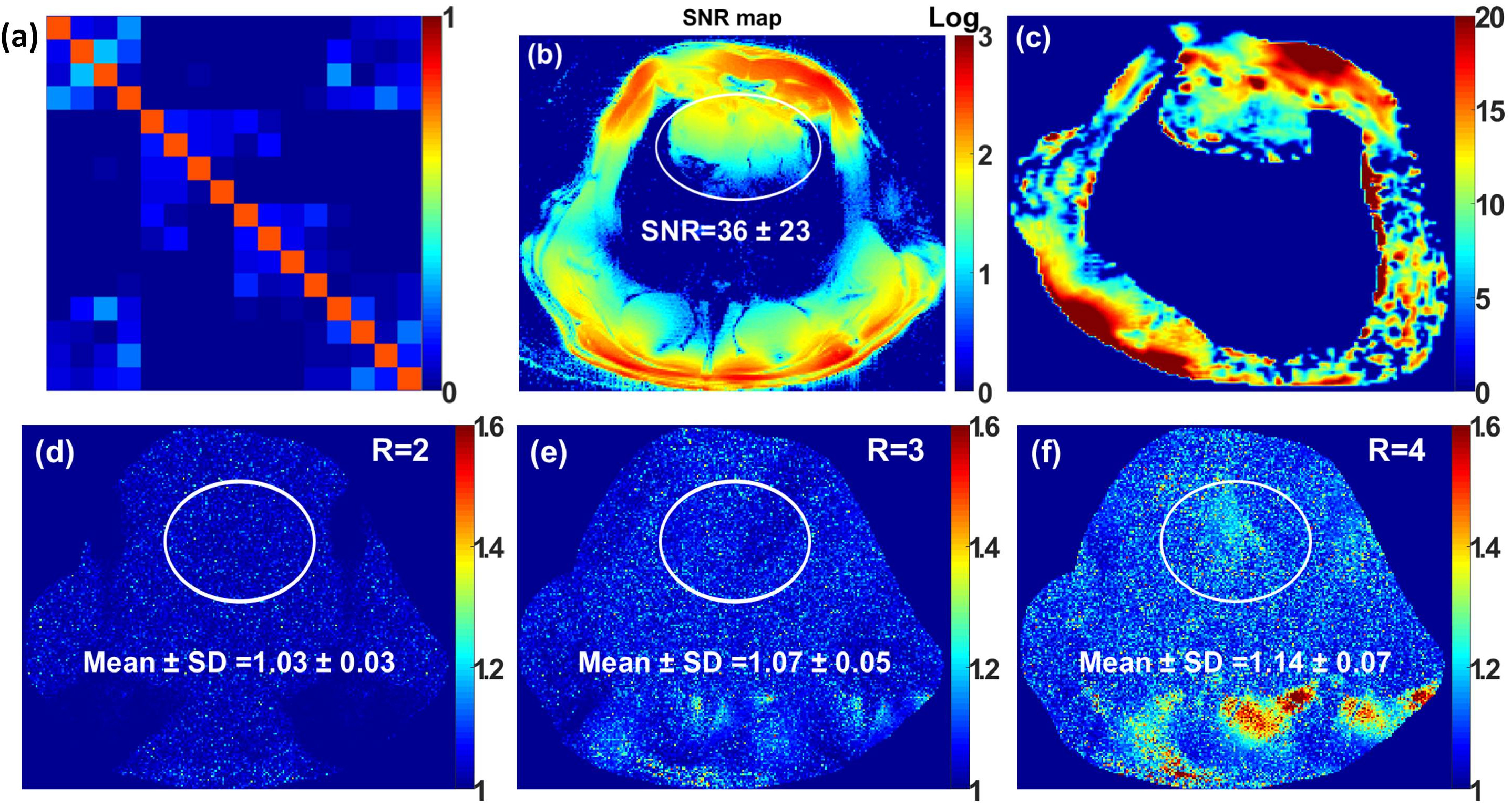
Figure 4 Noise correlation matrix (a), SNR map (b), FA map
(c), and g-factor maps of R = 2, 3, and 4 for an ex-vivo pig with acceleration
in the L/R direction (d)-(f) acquired using the dedicated pig cardiac array.
The mean ± SD of g-factor were computed in the heart ROI.
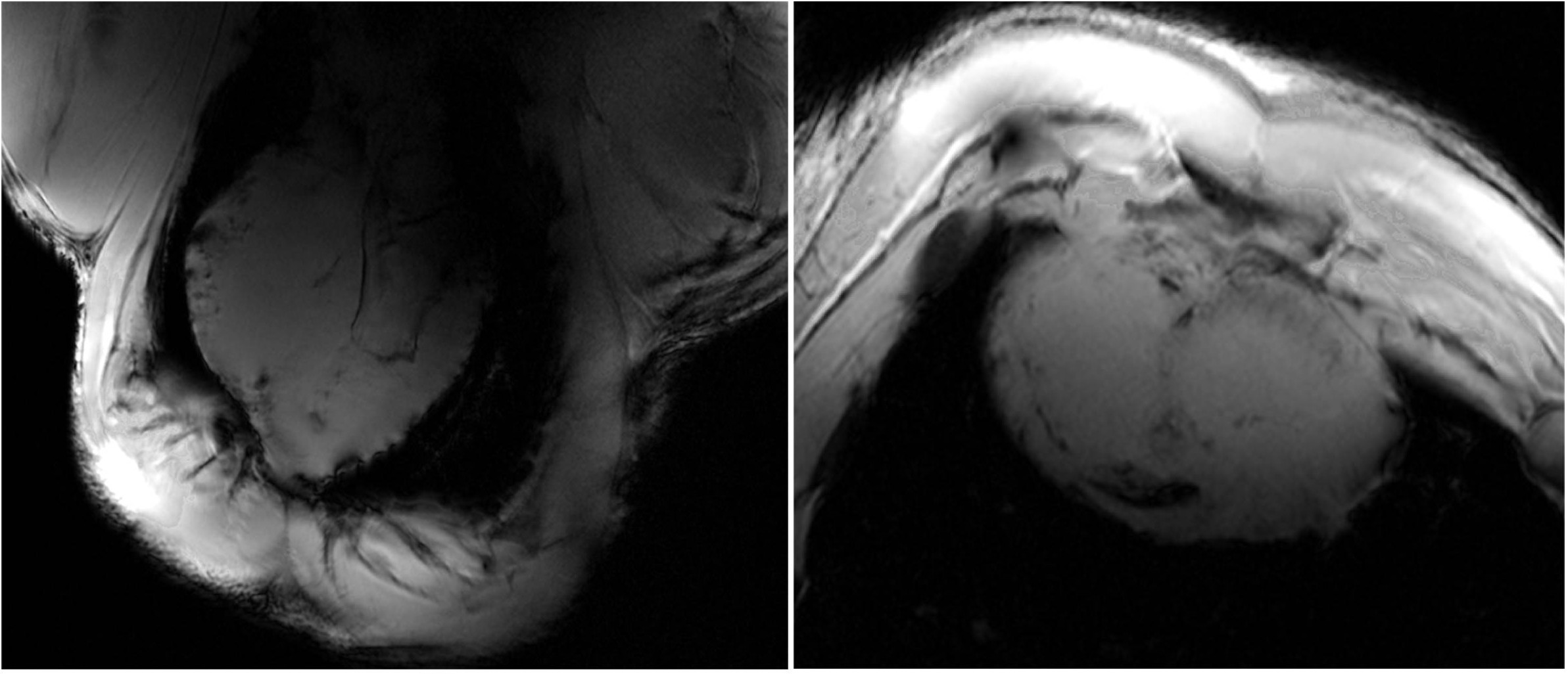
Figure 5 High resolution (0.3 mm × 0.3 mm) ex-vivo LA (left)
and SA (right) views of the pig heart acquired using the array.