4054
Self-decoupled Folded Dipole Antenna1Vanderbilt University Institute of Imaging Science, Nashville, TN, United States, 2Department of Radiology, Vanderbilt University Medical Center, Nashville, TN, United States, 3College of nuclear equipment and nuclear engineering, Yantai University, Yantai, China
Synopsis
In ultra-high-field MRI, both curl-free (dipole-like) and divergence-free current patterns (loop-like) are desired for better parallel transmission performance as well as to approach the ultimate receive performance for deep tissues. But decoupling dipole antennas is still a challenging topic. However, as shown in previous work, the strongest coupling in a dipole array is actually end-to-end between elements. Another challenge when using dipoles in dense arrays comes from their length, 45 cm at 300 MHz. We propose a novel, folded figure-of-eight (Fo8) configuration to shorten the dipole and simultaneously make it self-decoupled from others.
Purpose:
In ultra-high-field MRI, both curl-free (dipole-like) and divergence-free current patterns (loop-like) are desired for better parallel transmission performance as well as to approach the ultimate receive performance for deep tissues [1-6]. Several decoupling methodologies have been successfully developed for loop coils, but decoupling dipole antennas is still a challenging topic[7,8]. However, as shown in previous work, the strongest coupling in a dipole array is actually end-to-end between elements [9]. Although adjacent rows can be rotated to reduce this kind of coupling, this constrains the array layout and is feasible only for limited numbers of rows. Another challenge when using dipoles in dense arrays comes from their length, 45 cm at 300 MHz. We propose a novel, folded figure-of-eight (Fo8) configuration to shorten the dipole and simultaneously make it self-decoupled from others.Methods:
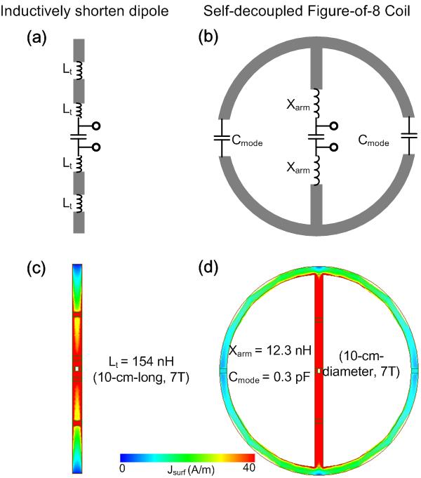
Figures 1a and 1b illustrate an inductively shortened dipole and a self-decoupled Fo8 coil. Similar to previous descriptions of self-decoupled coils [9], this Fo8 coil can be seen as a combination of two modes: the dipole mode and a Fo8-loop mode. The dipole mode couples electrically (coupling constant ke) while Fo8-loop modes couple magnetically (km). The values of ke and km have opposite signs, and their magnitudes can be changed by adjusting the value of Cmode. Therefore, the Fo8-coil can be self-decoupled when km+ke=0. At ultrahigh fields, Cmode typically has a small value/high impedance (0.3 pF for a 10-cm-diameter coil at 7T), and the current and electromagnetic (EM) field are dominated only by the middle conductor, as shown in Figures 1c and 1d. Therefore, it is expected to have similar EM fields as those of a straight dipole, and the self-decoupled Fo8 coil can be seen as a kind of folded dipole.We numerically evaluated pairs of end-to-end Fo8 coils for different coil sizes and different static magnetic fields. The simulations were performed using the FEM solver in HFSS (ANSYS, Canonsburg, PA, USA). All coils were wrapped around a cylindrical phantom (б =0.46 /0.55/0.60 S/m and ξr = 63.1/51.9/49.8 at 3T/7T/9.4T) with a separation of 1 cm. The diameters of the cylindrical phantoms were 10 cm. Coil conductors were modeled as copper sheets with a conductivity of 5.8 × 10⁷ S/m, and capacitors and inductors were modeled as lossy components with series resistance. To maximally match the current pattern of a straight dipole and obtain acceptable element isolation, we choose the smallest value of Cmode that maintained the parameter S21 < -15 dB. We compared the B1 efficiency of the self-decoupled Fo8 dipoles with those of straight dipoles of the same length.
Results and Discussions:
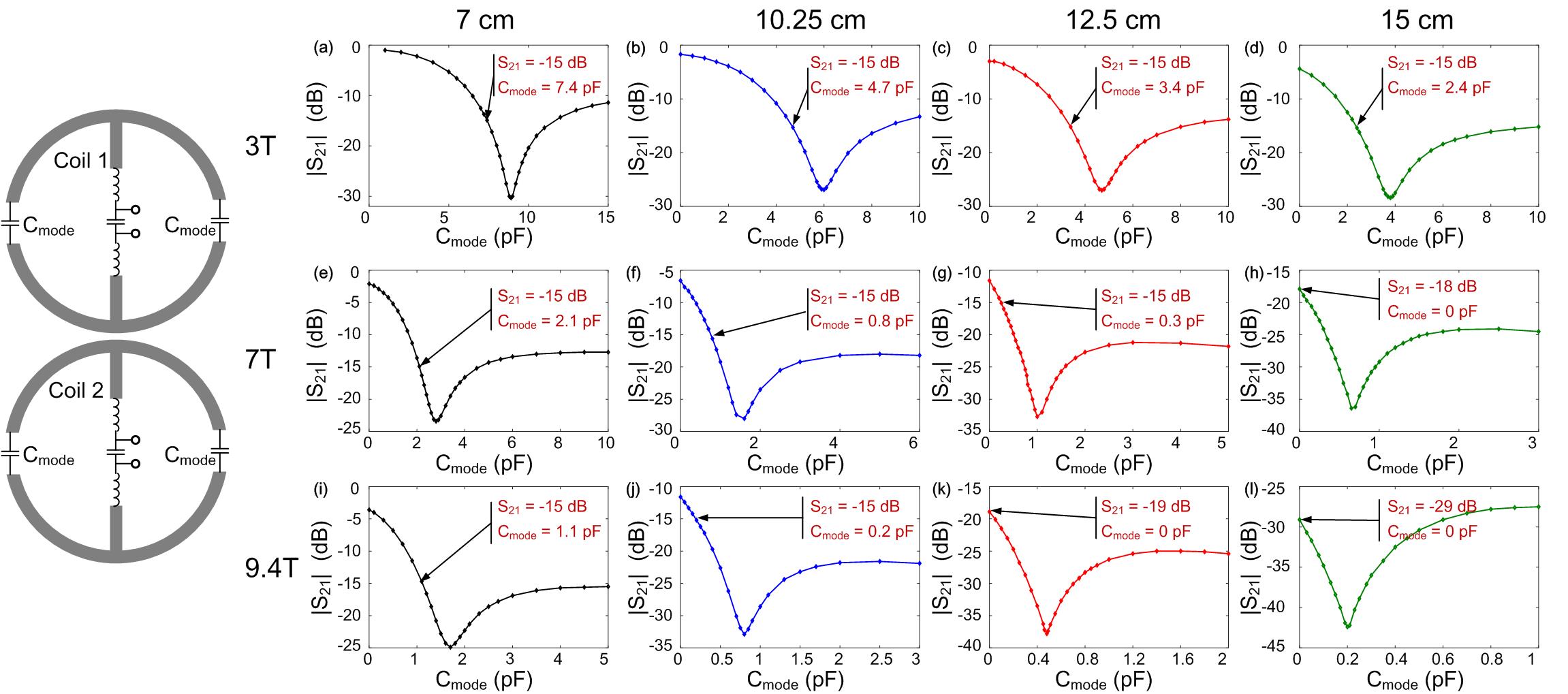
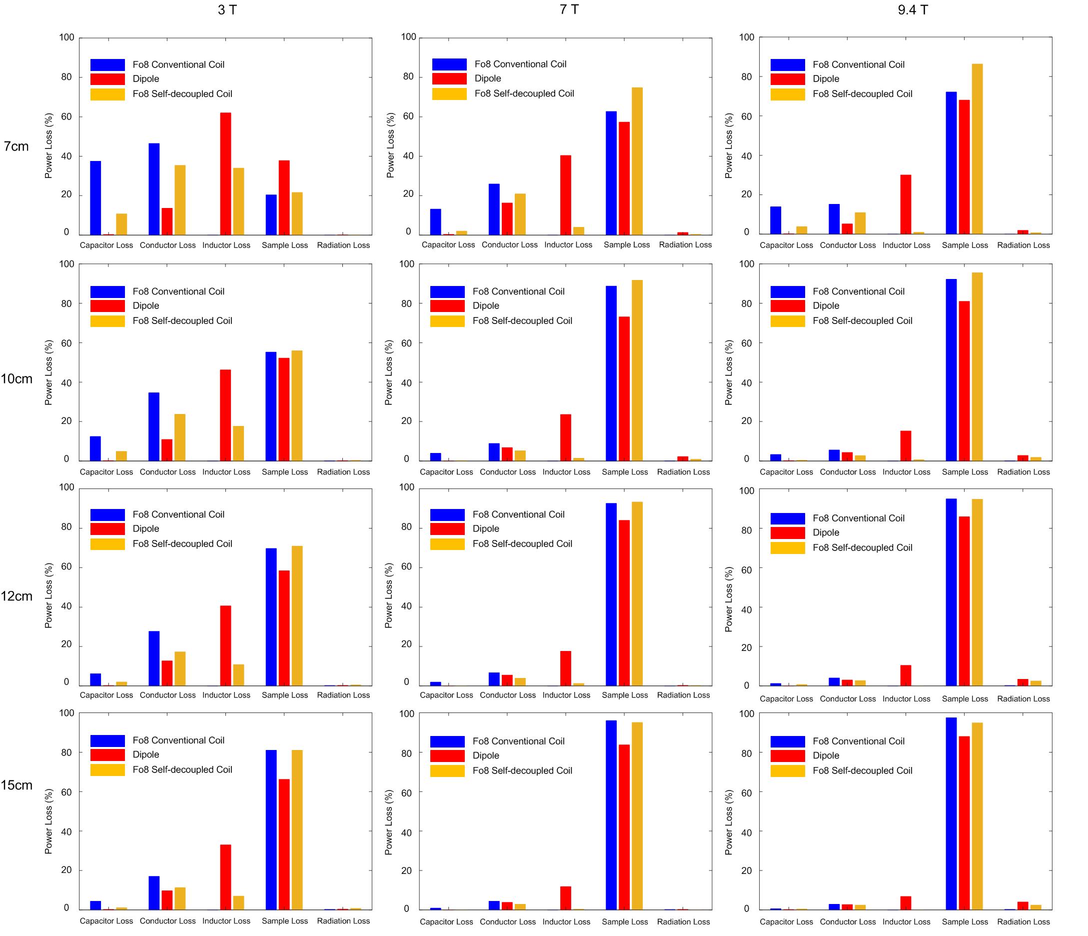
Figure 2 shows the calculated S21 values versus the value of Cmode. The required Cmode decreases as the coil size or magnetic field increases. For a 15cm-diameter coil at 7T and 12.5-cm-diameter coils at 9.4T, the S21 decoupling performance can achieve -15 dB even with Cmode = 0 pF, i.e., with open circuits.Figure 3 shows the result of power loss analyses with the same input power. For the inductively shortened dipole, to reduce the long dipole to ~10 cm, large inductors are required and thus induce considerable power loss/received thermal noise in the inductors. On the other hand, power losses are much smaller in self-decoupled Fo8 dipoles as smaller inductors are required. For example, for a 7T 10-cm diameter coil, the power losses from inductors are 21% and 4% for the shortened dipole and self-decoupled Fo8 coil, respectively.
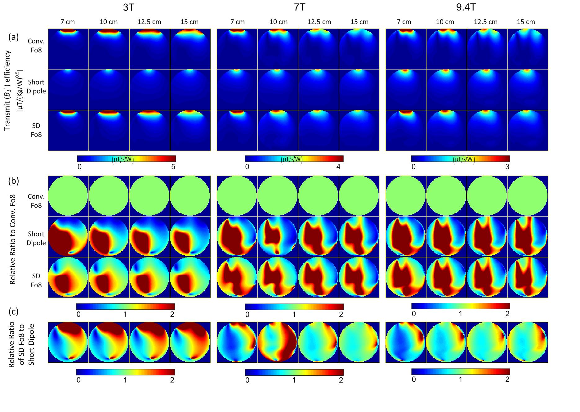
Figure 4a shows the simulated transmit efficiency (B1+/√power) maps, and Figure 4b shows their relative ratio compared to conventional Fo8 coils. Cmode has a relatively large value (2.4-7.4 pF, i.e., low impedance) at 3T, so the self-decoupled Fo8 coils have similar B1 maps as the conventional Fo8 coil. At 7T and 9.4T, however, they exhibit similar B1 patterns as the short dipole. Note that the self-decoupled coil has considerably higher B1 efficiency compared to the inductively shortened dipole when its length ≤10 cm at 7T and ≤12 cm at 9.4T, corresponding to much lower losses in the inductors (Figure 3).
Here, Cmode is chosen to decouple end-to-end elements (typically in different rows), and the coupling between the side-by-side elements is not considered. However, we found that the coupling between two side-by-side self-decoupled Fo8 dipoles can achieve -16 dB even without any decoupling treatments (Figure 5a and 5c). Another variety of dipole folds the dipole horizontally into a vertical loop (Figure 5b) [11,12]. Similarly, it can also be decoupled by choosing a suitable value for Cmode, as shown in Figure 5d.
Conclusion:
Folded dipole antennas (either folded vertically or horizontally into a Fo8 shape) can be self-decoupled from other elements by adjusting the distribution of impedances. At ultra-high fields, a self-decoupled folded dipole has a similar current and thus B1 pattern as the straight dipole, which should improve the transmission and receive performance when combined with loop coils. In addition to the improved decoupling performance, we found that the self-decoupled folded dipole outperforms the inductively-shortened dipole in terms of B1 efficiency.Acknowledgements
No acknowledgement found.References
1. Lattanzi, R., Wiggins, G. C., Zhang, B., Duan, Q., Brown, R., & Sodickson, D. K. (2018). Approaching ultimate intrinsic signal‐to‐noise ratio with loop and dipole antennas. Magnetic resonance in medicine, 79(3), 1789-1803.
2. Pfrommer, A., & Henning, A. (2017). On the contribution of curl‐free current patterns to the ultimate intrinsic signal‐to‐noise ratio at ultra‐high field strength. NMR in Biomedicine, 30(5), e3691.
3. Guérin, B., Villena, J. F., Polimeridis, A. G., Adalsteinsson, E., Daniel, L., White, J. K., & Wald, L. L. (2017). The ultimate signal‐to‐noise ratio in realistic body models. Magnetic resonance in medicine, 78(5), 1969-1980.
4. Ertürk, M. A., Raaijmakers, A. J., Adriany, G., Uğurbil, K., & Metzger, G. J. (2017). A 16‐channel combined loop‐dipole transceiver array for 7 T esla body MRI. Magnetic resonance in medicine, 77(2), 884-894.
5. Eryaman, Y., Guerin, B., Kosior, R., Adalsteinsson, E., & Wald, L. L. (2013). Combined loop+ dipole arrays for 7 T brain imaging. In Proc 21st Annual Meeting ISMRM, Salt Lake City.
6. Raaijmakers, A. J., Italiaander, M., Voogt, I. J., Luijten, P. R., Hoogduin, J. M., Klomp, D. W., & van Den Berg, C. A. (2016). The fractionated dipole antenna: A new antenna for body imaging at 7 T esla. Magnetic resonance in medicine, 75(3), 1366-1374.
7. Yan, X., Zhang, X., Wei, L., & Xue, R. (2015). Design and test of magnetic wall decoupling for dipole transmit/receive array for MR imaging at the ultrahigh field of 7T. Applied magnetic resonance, 46(1), 59-66.
8. Connell, I. R., & Menon, R. S. (2019). Shape Optimization of an Electric Dipole Array for 7 Tesla Neuroimaging. IEEE transactions on medical imaging.
9. Zhang, B., Chen, G., Cloos, M., Yu, Z., Walczyk, J., Collins, C., ... & Wiggins, G. (2017, September). 29-Channel receive-only dense dipole head array for 7T MRI. In 2017 International Conference on Electromagnetics in Advanced Applications (ICEAA) (pp. 1624-1627). IEEE.
10. Yan, X., Gore, J. C., & Grissom, W. A. (2018). Self-decoupled radiofrequency coils for magnetic resonance imaging. Nature communications, 9(1), 3481.
11. Lakshmanan, K., Cloos, M., Lattanzi, R., Sodickson, D., & Wiggins, G. (2014). The loopole antenna: capturing magnetic and electric dipole fields with a single structure to improve transmit and receive performance. In Proceedings of the 22nd Annual Meeting of ISMRM (p. 397).
12. Avdievich, N. I., Solomakha, G., Ruhm, L., Scheffler, K., & Henning, A. (2019). Evaluation of short folded dipole antennas as receive elements of ultra‐high‐field human head array. Magnetic resonance in medicine, 82(2), 811-824.
Figures