4053
A radiolucent 32-channel high impedance coil receive array to accelerate 3D imaging on hybrid 1.5 T MR-linac systems1Department of Radiotherapy, UMC Utrecht, Utrecht, Netherlands, 2Computational Imaging Group for MRI diagnostics and therapy, Centre for Image Sciences, UMC Utrecht, Utrecht, Netherlands, 3Department of Radiology, UMC Utrecht, Utrecht, Netherlands, 4Tesla Dynamic Coils, Zaltbommel, Netherlands
Synopsis
High impedance coils (HICs) offer major advantages for use during MRI-guided radiotherapy (MRIgRT), as they lack lumped elements that can attenuate radiation. Furthermore, their flexibility and low channel coupling simplify high-density array development and enable on-body placement.
Here, we present a fully functional 32-channel HIC array, confirmed its radiation transparency (radiolucency) and compared the imaging performance with the current clinical (LIC-based) array.
Dosimetrically, no clinically significant attenuation was caused by the array. Imaging-wise, the prototype showed higher SNR values and lower g-factors, thus allowing for faster imaging.
In conclusion, our 32-channel array can accelerate all imaging for MRIgRT applications.
Introduction
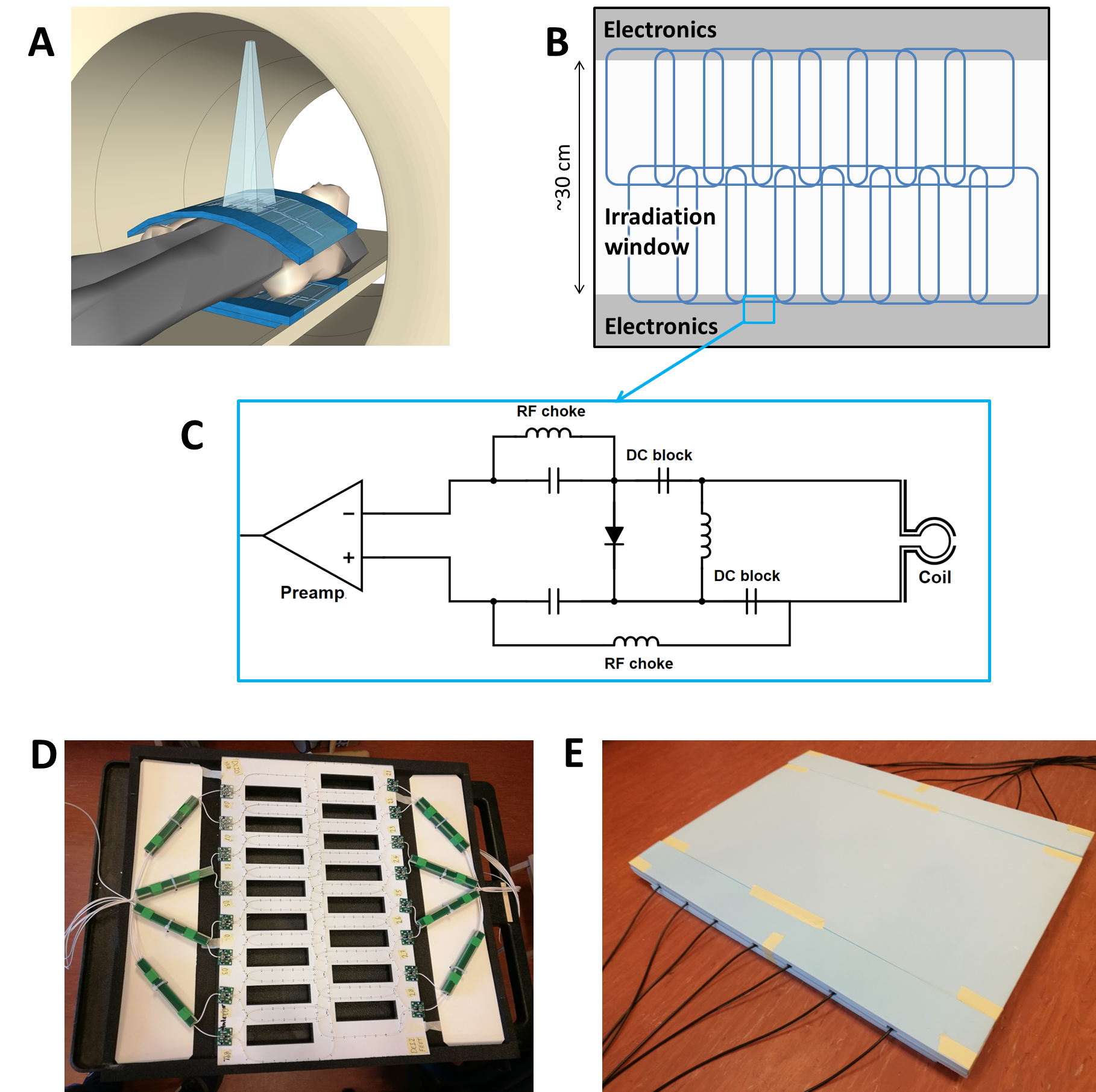
The 1.5 T Unity MR-linac (Elekta AB, Stockholm, Sweden) features an 8-channel clinical receive array that is placed at a distance of approximately 2 to 5 cm from the patient. The limited channel count and distance to the patient reduce the parallel imaging (PI) performance and signal-to-noise ratio (SNR). Consequently, real-time motion monitoring of tumors and surrounding organs during radiotherapy treatments is currently limited to 2D planes or low-resolution 3D volumes. To overcome this limitation, Zijlema et al.1 described the feasibility and design of a 32-channel on-body receive array that uses high impedance coils (HICs) to obtain the desired flexibility and radiation transparency (radiolucency). Besides their radiolucent properties, HICs exhibit low channel coupling, thereby simplifying high density array development.1,2In this work, we manufactured a preclinical 32-channel prototype based on the aforementioned design and verified its radiolucency. Subsequently, we performed a safety analysis for in-vivo usage and assessed the (in-vivo) imaging performance in terms of SNR and PI performance, which was compared to the current clinical array.
Methods
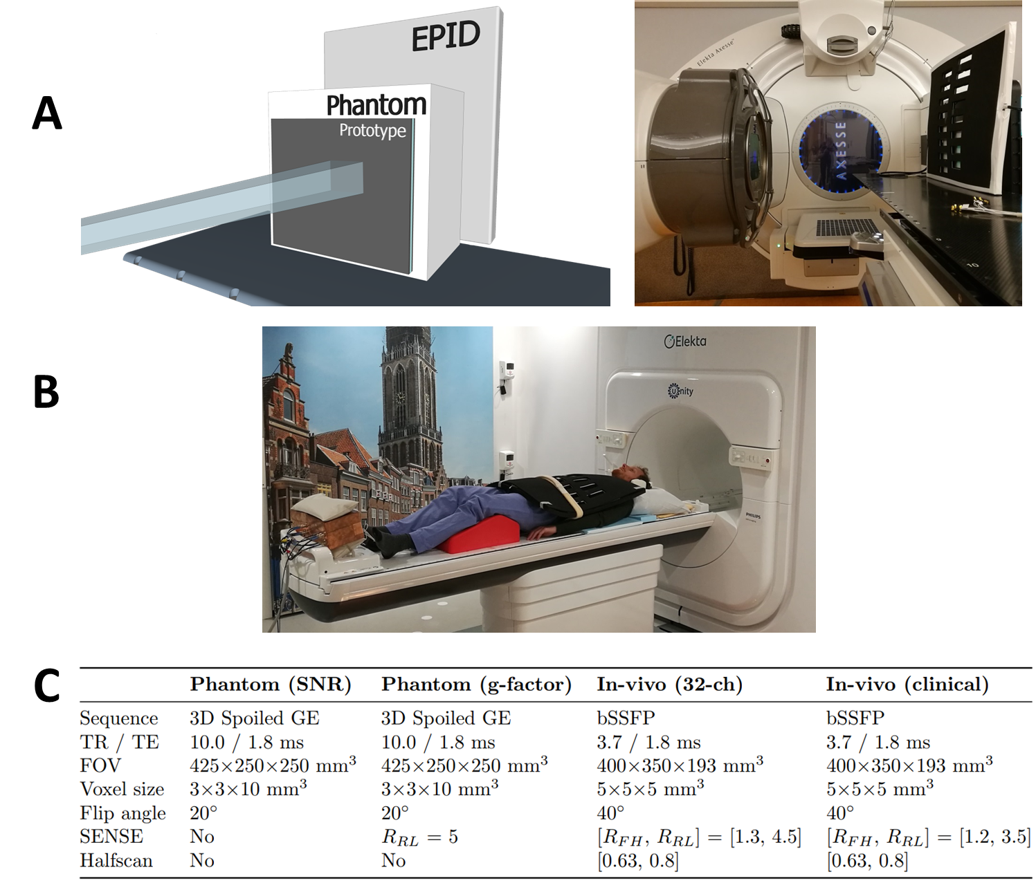
Construction: Based on the design of Zijlema et al.1, a 32-channel was constructed (Figure 1). Two 16-channel coil mats were created by sewing HICs (Alphawire 9432, ⌀1.1 mm) on a thin plastic sheet. A 15 mm foam layer was placed between the coil mat and the patient to avoid high surface doses.1 A safety analysis of the full array was performed to ensure volunteer safety by identifying potential risks and implementing design mitigations.3Dosimetry: Dose changes at 10 cm depth were investigated by delivering a 10×10 cm2 beams (100 MU) from 90° on an Elekta Synergy linear accelerator with and without a coil element present (Figure 2a). The electronic portal imaging device (EPID) was used to acquire 100-frame signal averages (pixel size: 0.35×0.35 mm2) that covered the full beam delivery. This data was normalized2 and the attenuation map $$$A_{prototype}$$$ was then calculated with:1,4
$$A_{prototype}=(S_{prototype}-S_{no_{ }prototype})/S_{no_{ }prototype}.$$
The single-beam attenuation properties of the anterior elements of the prototype and Unity clinical array were compared. Both posterior elements have a fixed position and can therefore be taken into account during treatment planning. These will therefore not lead to dose changes during treatments.
Imaging: All imaging was performed on a 1.5 T Elekta Unity MR-linac. The performance of the 32-channel prototype was compared to the 8-channel clinical array (Figure 2b). First, SNR maps5 were generated from 3D phantom acquisitions with a dynamic noise scan (Figure 2c). Noise correlation matrices were generated by calculating the Pearson correlation coefficients from the noise-only pre-scan. Subsequently, g-factor maps were generated from cartesian-undersampled 3D acquisitions (Figure 2c) to assess the acceleration performance.
Finally, in-vivo data were acquired of volunteers. Highly-accelerated 3D cine MRI was performed (Figure 2c) to demonstrate the 3D anatomy tracking capabilities.
Results
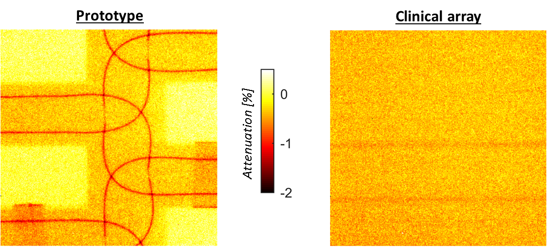
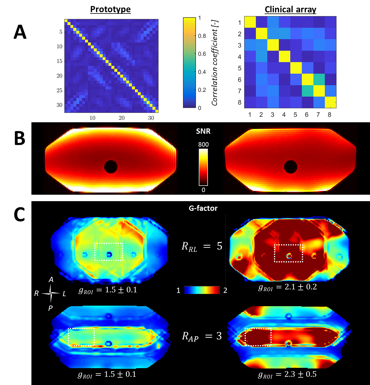
Dosimetry: Figure 3 shows the attenuation maps. Values are similar for the prototype and current clinical array, except for locations directly under coil conductors. Below a single coil conductor and overlapping point the attenuation is, at most, 0.9±0.1% and ~1.6%, respectively. Dose changes during treatments will be even lower, as treatments consist of multiple beams from several angles, which will smear out slight underdosages.Imaging: The prototype setup shows lower coupling coefficients than the clinical array (Figure 4a). In Figure 4b, a clear SNR increase is visible at the surfaces, while the SNR is similar in the center. G-factor maps show significantly lower g-factors when the 32-channel prototype is used (Figure 4c). Accelerated dynamic 3D imaging is shown in Figure 5. Reconstructed images acquired with the 32-channel prototype are significantly better than those acquired with the clinical array. Moreover, the temporal resolution is improved.
Discussion
The 32-channel prototype array was successfully manufactured and was approved for in-vivo use in our institute after passing a safety analysis.Dosimetry showed that the prototype attenuated a single beam, at most, 0.9-1.6%. In clinical practice, underdosages will be even lower, as clinical multi-angle beam or volumetric arc treatments smear out the slight underdosage. Consequently, the attenuation of the anterior element is not found to be clinically significant and can thus be omitted during treatment planning. The posterior element has a fixed position and can be taken into account during treatment planning. Body contour deformations due to on-body placement are compensated for by online replanning on the MR-linac6 and are therefore not an issue.
Imaging showed a clear improvement of the performance in comparison to the current clinical array of the MR-linac. The SNR at the surface and, most notably, PI performance improved, which allowed for faster imaging without concessions on the quality. Thereby, pre-beam imaging and intrafraction anatomy monitoring can be accelerated considerably. With the 32-channel array, 3D imaging with a second temporal resolution is now feasible and can provide high-quality motion estimates for treatment monitoring or adaptation, even with the relatively coarse resolution (5×5×5 mm3).7
Additionally, the 32-channel prototype’s low-attenuating properties could possibly be beneficial in hybrid PET/MRI.
Conclusion
Our 32-channel array that can be placed on the patient strongly improves the parallel imaging performance of the MR-linac for faster pre-beam imaging and high spatiotemporal monitoring of the 3D anatomy during treatments, while the array does not alter the delivered dose.Acknowledgements
This work is part of the research program HTSM with project number 15354, which is (partly) financed by the Netherlands Organization for Scientific Research (NWO). Assembled coil mats and support mechanics were kindly provided by Tesla Dynamic Coils (Zaltbommel, the Netherlands).References
- Zijlema, S. E. et al. Design and feasibility of a flexible, on-body, high impedance coil receive array for a 1.5 T MR-linac. Phys. Med. Biol. (2019) doi:10.1088/1361-6560/ab37a8.
- Zhang, B., Sodickson, D. K. & Cloos, M. A. A high-impedance detector-array glove for magnetic resonance imaging of the hand. Nat. Biomed. Eng. 2, 570–577 (2018).
- Rispoli, J. V. Best Practices for Safety Testing of Experimental RF Hardware: Report from the ISMRM Working Group. in Procs. ISMRM Workshop on MR Safety (2019).
- McDermott, L. N., Louwe, R. J. W., Sonke, J. J., van Herk, M. B. & Mijnheer, B. J. Dose-response and ghosting effects of an amorphous silicon electronic portal imaging device. Med. Phys. 31, 285–295 (2004).
- Kellman, P. & McVeigh, E. R. Image Reconstruction in SNR Units: A General Method for SNR Measurement. Magn. Reson. Med. 54, 1439–1447 (2005).
- Winkel, D. et al. Adaptive radiotherapy: The Elekta Unity MR-linac concept. Clin. Transl. Radiat. Oncol. 18, 54–59 (2019).
- Glitzner, M., Senneville, B. D. de, Lagendijk, J. J. W., Raaymakers, B. W. & Crijns, S. P. M. On-line 3D motion estimation using low resolution MRI. Phys. Med. Biol. 60, N301–N310 (2015).
Figures