4052
A Patient-Friendly Coil For Bilateral Carotid Artery Imaging1Radiology, New York University Langone Health, New York, NY, United States, 2Radiology, Weill Cornell Medical College, New York, NY, United States
Synopsis
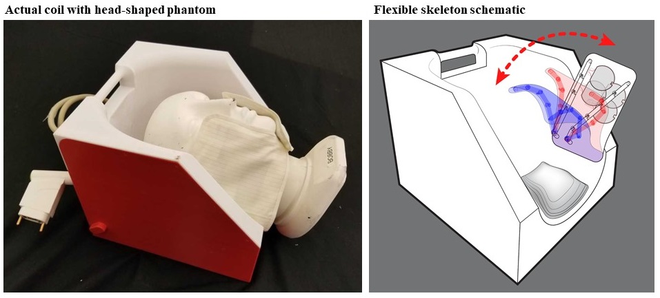
Carotid MRI imaging can be vital in preventing heart disease and stroke but is difficult due to variable neck anatomy. Traditional rigid coils have a hard time achieving a close fit on all patients which can result in SNR loss that is essential for delineating the thin vessel wall. We designed and implemented an 8-channel flexible coil by incorporating the resonators into tailored cloth sleeves with integrated semi-rigid skeletons and a head cradle that provided the means for straightforward patient positioning and comfort, and a contoured fit for high SNR.
Introduction
Cardiovascular MRI can characterize atherosclerotic plaque in the carotid arteries and thereby is vital for predicting Ischaemic heart disease and stroke1,2 - two leading causes of death worldwide. Carotid artery MRI is difficult due to motion and variable neck anatomy. The latter creates a significant challenge for traditional rigid coils to achieve a close fit on all patients while maintaining comfort, which can result in SNR loss that is essential for delineating the thin vessel wall. Our group previously introduced a flexible carotid coil3 based on the high-impedance coil (HIC) resonator4, which performed better than a conventional coil but was nonetheless difficult to position in a streamlined manner. In this work, we improved the coil by incorporating the flexible resonators into tailored sleeves with integrated semi-rigid skeletons and a head cradle. This mechanical system provided the means for straightforward patient positioning and a contoured fit for high SNR.Methods
We built the array with the goals of maximizing SNR and patient comfort using mechanically flexible coils without bulky, rigid components that easily conform to the anatomy. The highly flexible coils were packaged into tailored cloth sleeves with integrated chin contours and 3D printed skeletons that securely conformed to the anatomy in a personalized manner (Figure 1). The flexible coils were attached to a 3D printed head cradle that fostered the so-called “extended neck position” in which the neck is elevated anterior such that the arteries move toward the periphery and are therefore easier to image5.The array consisted of two sets of 4 HICs; one set to cover the left and one to cover the right carotid artery. The coils (∅= 6cm) were made of micro-coaxial cables and tuned to 123.2 MHz in the presence of a head and neck phantom with realistic dielectric properties (εr = 65 and σ = 0.45 S/m)6. The coils along with miniaturized tuning and detuning circuitry were stitched onto the flexible cloth sleeves and arranged in an overlapped pattern for geometric decoupling. The detuning circuit was similar to that in reference 4 and was formed using two PIN diodes that short-circuit the inner and outer conductor of the coaxial cable during body coil excitation. A fuse was implemented in the circuitry for safety in the event of active detuning failure. To maintain mechanical flexibility of the coils, the bulky preamplifiers and phase-shifters were remotely located inside the head cradle. The coils were connected to the preamplifiers through coaxial cable and compensatory lumped-element phase-shifters to achieve reversed preamplifier decoupling.
The coil was evaluated on our 3T scanner (Prisma, Siemens, Erlangen, Germany) by comparing SNR in the phantom and in-vivo to that obtained with a state-of-the-art 64-channel head and neck coil, which is used in our Center in lieu of a dedicated carotid coil (Head/Neck 64, Siemens). High resolution in-vivo images were acquired using a 3D turbo spin echo sequence on a healthy volunteer.
Results and Conclusion
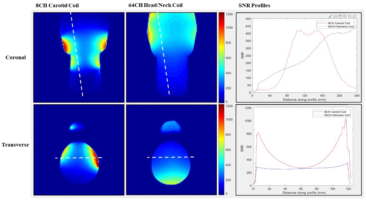
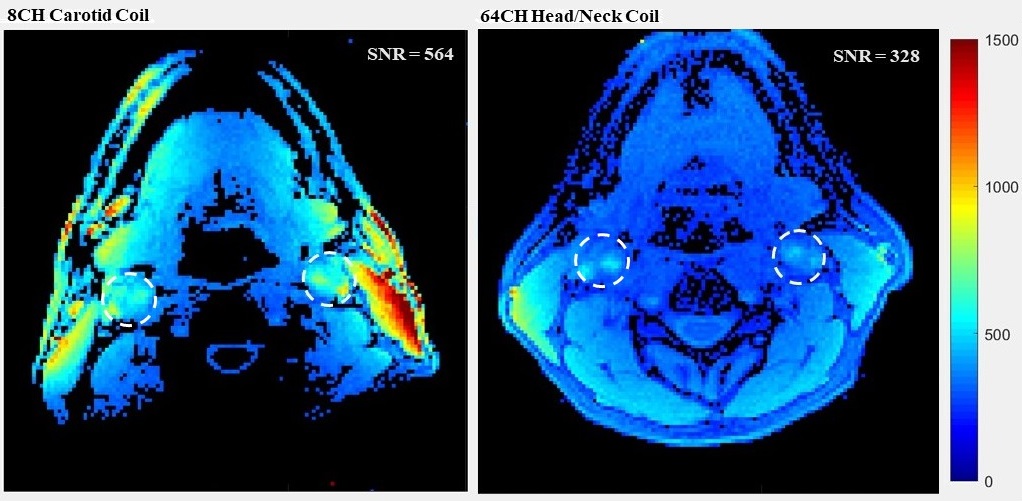
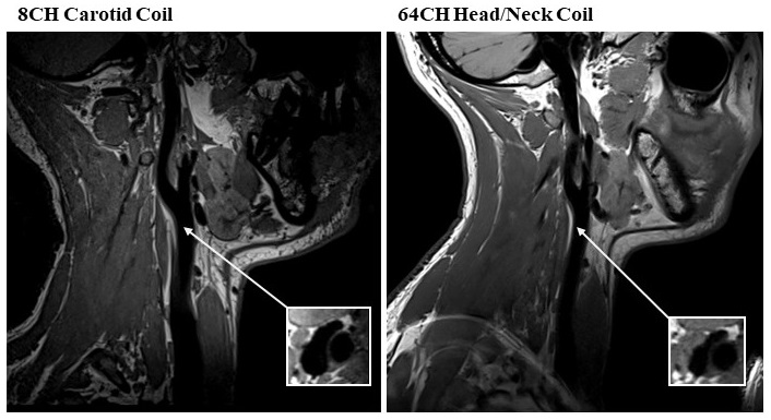
The SNR depth comparison from the phantom experiments is shown in Figure 2. The region of interest for carotid imaging is between 20 mm and 50 mm7; it can be seen that the 8 channel carotid coil provides over 50% SNR improvement at 40mm, and up to 200% gain at 20mm compared to the 64 channel head/neck coil. The profile through the coronal map shows the carotid coil has a longitudinal coverage of approximately 10.6 cm (measured as the full width at half maximum signal amplitude at the carotid artery depth), which is sufficient for most clinical protocols. In-vivo measurements showed that the 8-channel carotid coil provided 71% SNR gain near the carotid bifurcation (Figure 3). High-resolution fluid suppressed images show excellent delineation of the carotid bifurcation and no sign of plaque in the healthy volunteer (Figure 4).The prototype design utilized a collection of eight uniform 6-cm diameter coils. We are currently exploring with a range of geometries and expansion beyond 8-channels, using literature for guidance7,8,9,10,11 to further improve SNR. In conclusion, we designed and implemented an 8-channel coil for bilateral carotid artery imaging. Its flexible coils and housing system provided a close fit to the region of interest and greater SNR than the standard 64-channel clinical head and neck coil while maintaining patient comfort
Acknowledgements
This work was performed under the rubric of the Center for Advanced Imaging Innovation and Research (CAI2R, www.cai2r.net) at the New York University School of Medicine, which is an NIBIB Biomedical Technology Resource Center (NIH P41 EB017183). In addition, we would like to acknowledge Riccardo Lattanzi for providing the appropriate SNR tools and Karthik Lakshmanan for his contribution and help in the project.References
1. Cai JM, Hatsukami TS, Ferguson MS, Small R, Polissar NL, Yuan C. Classification of human carotid atherosclerotic lesions with in vivo multicontrast magnetic resonance imaging. Circulation 2002;106(11):1368-73.
2. Takaya N, Yuan C, Chu B, Saam T, Underhill H, Cai J, Tran N, Polissar NL, Isaac C, Ferguson MS, Garden GA, Cramer SC, Maravilla KR, Hashimoto B, Hatsukami TS. Association between carotid plaque characteristics and subsequent ischemic cerebrovascular events: a prospective assessment with MRI--initial results. Stroke 2006;37(3):818-23.
3. Zhang B, Cloos MA, Yang J, Nguyen TD, Brown R. Ultra-flexible 3T HIC Receive Array for Carotid Imaging. Institute of Electrical and Electronics Engineers. 2019. September 9. DOI: 10.1109/ICEAA.2019.8878950
4. Zhang, B., Sodickson, D. K. & Cloos, M. A. A high-impedance detector-array glove for magnetic resonance imaging of the hand. Nat. Biomed. Eng. 2018; DOI: 10.1038/s41551-018-0233-y.
5. Singh N, Moody AR, Roifman I, Bluemke DA, Zavodni AE. Advanced MRI for carotid plaque imaging. The international journal of cardiovascular imaging. 2016. January 1;32(1):83–9. 10.1007/s10554-015-0743-6
6. Ianniello C, de Zwart JA, Duan QI, et al. Synthesized tissue‐equivalent dielectric phantoms using salt and polyvinylpyrrolidone solutions. Magn Reson Med. 2018; 80: 413– 419.
7. Tate Q, Kim S-E, Treiman G, Parker DL, Hadley JR. Increased vessel depiction of the carotid bifurcation with a specialized 16-channel phased array coil at 3T. Magn Reson Med 2013;69:1486–1493.11.
8. Beck MJ, Parker DL, Bolster BD Jr, Kim SE, McNally JS, Treiman GS, Hadley JR. Interchangeable neck shape- specific coils for a clinically realizable anterior neck phased array system. Magn Reson Med 2017;78(6): 2460-2468.
9. Hayes CE, Mathis CM, Yuan C. Surface coil phased arrays for high-resolution imaging of the carotid arteries. J Magn Reson Imaging 1996;6:109–112.9.
10. Balu N, Yarnykh VL, Scholnick J, Chu B, Yuan C, Hayes C. Improvements in carotid plaque imaging using a new eight-element phased array coil at 3T. J Magn Reson Imaging 2009;30:1209–1214.10.
11. Hu X, Zhang L, Zhang X, Zhu H, Chen X, Zhang Y, Chung Y-C, Liu X, Zheng H, Li Y. An 8-channel RF coil array for carotid artery MR imaging in humans at 3 T. J Med Phys 2016;43:1897–1906.
12. Kellman P, McVeigh ER. Image reconstruction in SNR units: a general method for SNR measurement. Magn Reson Med 2005;54(6):1439-1447.
Figures