4051
Design and evaluation of a dual-tuned circular dipole antenna up to 14T MRI1Institute of Neuroscience and Medicine 4, INM-4, Forschungszentrum Jülich, Jülich, Germany, 2Institute of Neuroscience and Medicine 11, INM-11, JARA, Forschungszentrum Jülich, Jülich, Germany, 3JARA - BRAIN - Translational Medicine, Aachen, Germany, 4Department of Neurology, RWTH Aachen University, Aachen, Germany
Synopsis
When the field strength of MRI is increased to 14T, the capacitor values required to tune a conventional loop coil become extremely small. For 7T MRI, the circular dipole antenna has been introduced and evaluated as the array structure and new decoupling method. In this study, we modified a circular dipole antenna to a dual-tuned circuit by using an LC trap. The coil operates as a circular dipole antenna for the proton signal as the trap blocks 1H current and operates as a conventional loop at the X-nuclei frequency. The dual-tuned circular dipole antenna was evaluated up to 14T frequency.
Ultra-high field MRI provides high SNR and excellent contrast as well as the potential for X-nuclei measurements. The development of higher field magnets of up to 14T is being planned and evaluated in the community. A dual-tuned RF coil with a single-port has been utilised for 1H/X-nuclei application and was extended to a 30 channel receive-only array for 1H/31P application at 7T. 1 One common approach for the design of the phased receive array is the use of a soccer ball geometry that consists of, for example, 8.5 cm inner diameter circular loops. 2 The capacitor values required to tune the circular loop coil are around 1.4 pF, 0.79 pF, 0.5 pF and 0.35 pF at 7T, 9.4T, 11.7T and 14T MRI, respectively. However, as the use of numerous discrete series capacitors degrades the SNR due to the series resistance of the capacitors, this approach is not viable at UHF.
The required length of the dipole antenna is, for example, 50 cm at 7T, which is rather long for head imaging applications. There are, however, several methods to optimise the length including bending the dipole antenna around the head 3 or modifying the dipole antenna to a circular shape. 4
In this study, we redesigned a circular dipole antenna to work at dual-resonance by using an LC trap. The trap blocks the 1H current so that the dual-tuned circular dipole antenna operates as a dipole antenna at the 1H frequency, while the same coil resonates as a conventional loop coil at the X-nuclei frequency since the trap does not block the X-nuclei frequency. The dual-tuned circular dipole antenna was simulated and evaluated on the bench and at 7T MRI. The performance results were compared to those of single-tuned conventional loops.
METHODS
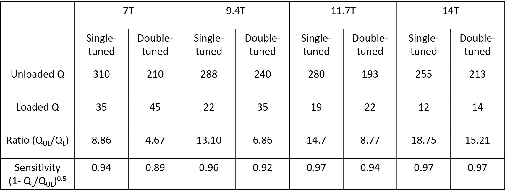
Fig. 1. shows a schematic of a circular dipole antenna and a dual-tuned circular dipole antenna. To evaluate tuning and current patterns, FIT simulation was conducted using CST. Based on co-simulation results, dual-tuned circular dipole antennas were built for use up to 14T. The inner diameter of the circular dipole antenna was chosen to be 8.5 cm and the width was 0.5 cm. All antennae were loaded with a cylindrical phantom (diameter = 11 cm, length = 20 cm, ϵ = 80, and σ = 0.5 S/m) containing 1 g KH2PO4, 1.25 g NiSO4 × 6H2O and 2.6 g NaCl per litre. To evaluate the 31P sensitivity at different field strengths, the loaded/unloaded Q-ratios were measured. The relative sensitivity 5 was calculated using loaded/unloaded Q-ratios and the sensitivity of dual-tuned circular dipole antenna was compared with those of single-tuned reference coils tuned at X-nuclei frequencies up to 14T. A CSI was used to acquire 31P spectra with parameters of TR = 2000 ms, TE = 0.23 ms, average = 64, voxel size = 25 × 25 × 25 mm3 and weighted phase encoding.
RESULTS
Fig. 2. shows S11 of dual-tuned circular dipole antennas tuned to 1H/31P frequencies at 7T and 14T MRI. The bench measurement was reproducible with simulation results. Table 1 shows loaded/unloaded Q-ratio and corresponding relative sensitivities at 31P frequencies. The dual-tuned circular dipole antenna provided approximately 95% sensitivity of a single-tuned loop at 7T. The difference between the sensitivity of the single-tuned loop and that of the dual-tuned circular dipole antenna then decreased as the field strength increased.
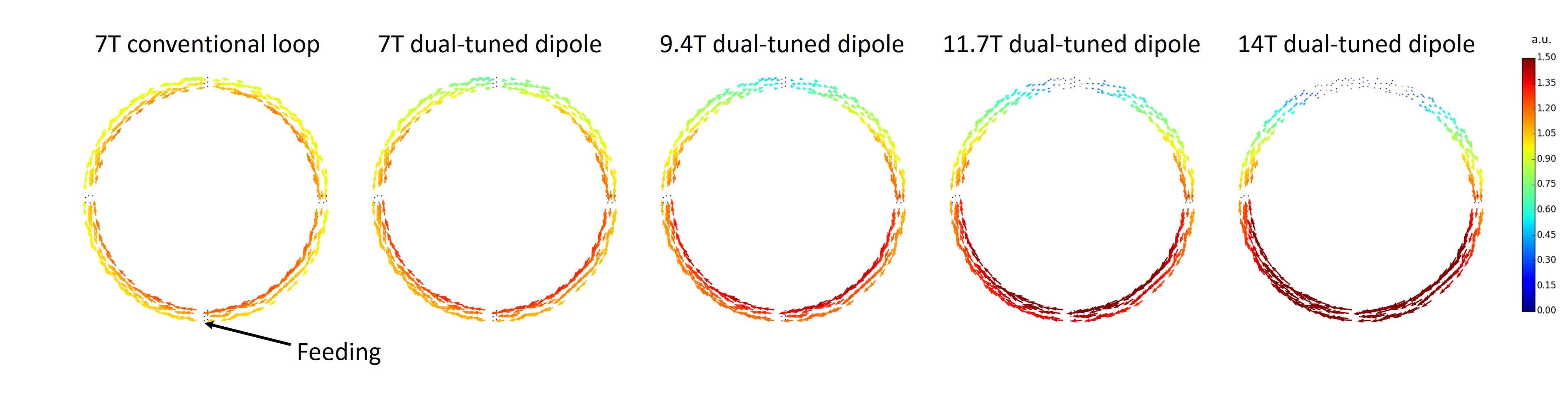
Fig. 3. shows 1H current distribution of conventional single-tuned loop coil at 7T and dual-tuned circular dipole antenna up to 14T. The conventional loop coil provided a distributed current pattern over the loop pattern while the dual-tuned circular dipole antenna shows a focused pattern near the feeding area, which can also be found in the dipole antenna (half-wavelength standing wave). The focused patterns became remarkable as field strength was increased. Fig. 4. shows CSI 31P spectra overlaid on the scout 1H image, indicating the independent transmit and receive at both 1H and 31P frequencies.
DISCUSSION
The signal loss at X-nuclei frequencies was evaluated by comparing the loaded/unloaded Q-ratio, while measuring Q-factors was not applicable at the 1H-frequency, since the loaded Q of the circular dipole antenna at 1H frequencies was too low to detect the 3 dB bandwidth of S21. In addition, an indirect sensitivity comparison by dividing the SNR by the flip angle was difficult since the flip angle distribution was very inhomogenous. At X-nuclei frequency, the sensitivity loss was less than 5%.
The focused pattern of the 1H current was notable as the field strength was increased. The focused current pattern resulted in a shifted transmit efficiency pattern near the port which was proportional to the degree of current focusing, while the average transmit efficiency over the whole phantom was identical to the conventional single-tuned loop coil.
CONCLUSION
The tuning and relative sensitivity of a new dual-tuned coil concept using the circular dipole antenna was evaluated up to 14T MRI. It was shown that the novel coil design provides minimum loss at X-nuclei frequencies and a wide tuning range of up to 14T with a single-port, making it a promising concept for multi-channel dual-tuned coil systems at extremely high field MRI.
Acknowledgements
No acknowledgement found.References
1. B. C. Rowland et al. Whole brain P MRSI at 7T with a dual-tuned receive array. Magnetic Resonance in Medicine. in press.
2. G. C. Wiggins, C. Triantafyllou, A. Potthast, et al. 32-channel 3 Tesla receive-only phased-array head coil with soccer-ball element geometry. Magn Reson Med. 2006; 56(1): 216–223
3. S. M. Hong, C. H. Choi, A. W. Magill, et al. Design of a quadrature 1H/31P coil using bent dipole antenna and 4-channel loop at 3T MRI. IEEE Transactions on Medical Imaging. 2018; 37(12) ; 2613 - 2618
4. K. Lakshmanan, M. Cloos, and G. C. Wiggins. Circular dipole and surface coil loop structures and methods for using the same. USPETENT. 2015 US20150137815A1.
5. A. Haase et al. NMR probeheads for in vivo applications. Concepts in Magnetic Resonance. 2000; 12(6): 361–388
Figures