4050
The Very RF Hungry Caterpillar Trap (Highly Flexible, Distributed System of Toroid Cable Traps)
Ekin Karasan1, Victor Taracila2, Fraser Robb2, and Michael Lustig1
1Department of Electrical Engineering, University of California, Berkeley, CA, United States, 2GE Healthcare, Coils, Aurora, OH, United States
1Department of Electrical Engineering, University of California, Berkeley, CA, United States, 2GE Healthcare, Coils, Aurora, OH, United States
Synopsis
“In the light of the moon a little egg lays on a leaf”[7]
Management of cabling connecting coil arrays to system remains the nightmare of RF-engineers. Coupling within arrays to cabling reduces performance, and coupling to transmit field causes high shield currents. Consequently, traps are placed on conductors. To provide high blocking, traps are rigid, large and often heavy, hindering flexibility. Instead of a few high blocking traps, we propose a distributed system of small, elastic traps. We leverage self-shielded resonant toroids forming a caterpillar-like structure. We show that this design can attenuate shield currents while being robust to flexing.
Introduction
“On Sunday.. out of the egg comes a tiny and very hungry caterpillar”[7]Common mode currents occur on conducting wires within the bore of the scanner, for example, on the shield of coaxial cables between coils and main system. These currents effect coil performance, result in B1 inhomogeneities and pose serious safety hazards such as RF burns[1]. To mitigate shield currents, resonant cable traps are placed at certain intervals along cable (Figure 1a). While many designs exist[2], the basic principle is similar -- creating a high impedance through a resonance LC tank. These can either leverage the conductor itself, or inductively couple, i.e. a “floating” trap[3]. Floating traps can be easily fitted and positioned but don’t allow cable to be flexed and are only effective if placed in regions of highest shield current. These structures couple, thus, cannot be place closely, and need to have a length larger than radius in order to not interact with the B1 field and perform efficiently[4]. For this reason, a few large, high performance structures are used. Here, we propose a new, distributed design of traps where smaller self-shielded substructures are placed along the full length of cable (Figure 1b). These self-shielded structures do not couple to main field or each other thus requiring no shielding. With this distributed design, any bending is unlikely to impact overall structure allowing the cable to still be flexible while providing sufficient attenuation (Figure 1c).
Methods
The substructures were chosen to be resonant toroids as they are mostly self-shielded, especially with increased number of windings. Toroids have previously been used in traps but as the inductor for large, inductively coupling structures[5]. Our smaller traps can be laid out, along the entirety of the cable in a caterpillar-like structure without impeding its flexibility. The traps are tuned using four capacitors, one of which is variable, so that electrical field due to capacitors is uniformly distributed around structure.Simulations
Initially, simulations were conducted with air-core toroids to determine optimal parameters of the overall structure for a fixed wire and toroid thickness($$$t$$$) including diameter of toroids($$$d$$$), separation between toroids($$$s$$$) and number of windings in each toroid($$$N$$$) as shown in Figure 2. Simulation results normalized by total length($$$l$$$) of the trap show that a 24-turn toroid outperforms a 12-turn toroid while slight coupling is observed between toroids with increased toroid diameter as seen from the reduced performance of the 12mm diameter toroid with $$$s=2$$$mm compared to $$$s=5$$$mm. From simulations, optimal parameters were determined to be $$$d=9$$$mm, $$$s=5$$$mm and $$$N=24$$$ and the structure built accordingly.
Fabrication
The design of a substructure is shown in Figure 3a. To allow overall flexibility, the structure is manufactured on a low-loss Polydimethylsiloxan(PDMS) elastic substrate. A mold is designed (Figure 3b) with a slit for the wire and slots for the four capacitors. The mold is 3D printed and used for injection molding. Toroids are hand wound with magnet wire and the capacitors soldered on resulting in an elastic structure (Figure 3c).
Benchtop
Tests were conducted with setup in Figure 4a. Toroids were fitted on a 6.80mm diameter cable. The performance of the structure with different numbers of toroids was measured and compared to simulations and theoretical ideal calculations, that assume low loss wires, vacuum medium, and no interactions between toroids.
Scans
B1 distortion experiments were performed on an GE MR750WGE (Waukesha, Wisconsin). Two cables were cut to the length of a resonant dipole for 127.7MHz. Three B1-mapping measurements[6], with a flip angle of 30o, were performed in a non-loading phantom. The first mapped the B1 field produced by the body transmitter alone. In the second, the resonant dipole was placed on the phantom, while measuring the B1 field in a slice 1.65 cm below wire. In the 3rd, a resonant dipole equipped with our caterpillar traps was placed in the same way and measured. To evaluate the performance while flexing the wire, we repeated the measurements, this time with a flip angle of 15o, by bending wires and placing them on the phantom as shown in Figure 5.
Results and Discussion
A comparison between ideal, simulations and benchtop measurements show that both simulations and benchtop measurements were inferior to the ideal providing 3.64dB and 4.96dB reduced attenuation for single toroid respectively (Figure 4b). The benchtop measurements are also slightly inferior to simulations due to decreased permeability of PDMS compared to air. Benchtop measurements show that a single toroid is able to obtain -5.11dB attenuation at a resonant frequency of 127.7 MHz attaining a Q-factor of 106, whereas a 7 toroid structure is able to obtain -22.82dB attenuation attaining a Q-factor exceeding 350 (Figure 4c). Figure 5 displays the results of the B1 distortion experiments. The B1 field maps are displayed, in degrees. Attenuation of the shield current by caterpillar traps are evident in both configurations.Conclusions
“Now he isn’t a little caterpillar. He is a big fat caterpillar”[7]Our distributed design splits the cable trap into smaller, self-shielded subcomponents. This study shows that our caterpillar traps can provide sufficient attenuation to shield currents while also maintaining flexibility, enabling the entire structure from coil to system to be light, flexible and convenient.
Acknowledgements
No acknowledgement found.References
- Beck BL, Peterson DM, Duensing GR, Fitzsimmons JR. 2000. Implications of Cable Shield Currents at 3.0 and 4.7 Tesla. Int Soc Magn Reson Med, Denver, CO. p 641.
- X. Yang and F. Fujita, “T/R switches, baluns, and detuning elements in MRI RF Coils,” Proc. Intl. Soc. Mag. Reson. Med. 14, Seattle, 2006.
- Burl, M., Chmielewski, T., & Braum, W. O. (2001). Patent No. US6593744B2.
- Seeber, D. A., J. Jevtic, and A. Menon. "Floating shield current suppression trap." Concepts in Magnetic Resonance Part B: Magnetic Resonance Engineering: An Educational Journal (2004): 26-31.
- Taracila V., Smith L., Stack C., Robb F. “Optimal Bazooka Balun Proportions,” Proc. Intl. Soc. Mag. Reson. Med. 27, Paris, 2018.
- Sacolick, Laura I et al. “B1 mapping by Bloch-Siegert shift.” Magnetic resonance in medicine vol. 63,5 (2010): 1315-22.
- Eric Carle “The Very Hungry Caterpillar” 1969, ISBN-10 0399226907
Figures
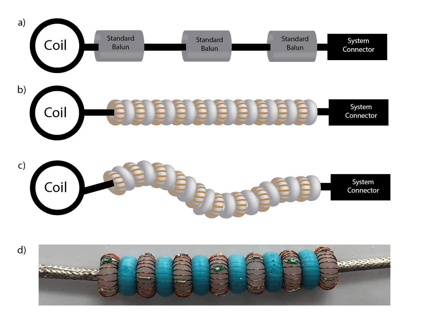
(a) Standard cable
traps and (b) our proposed caterpillar distributed design. Many smaller
toroidal traps are distributed across the length of the cable, separated by spacers.
(c) This design provides potential for the wire to be bent while still providing
sufficient RF attenuation. (d) Seven PDMS based elastic resonant-toroid trap
structure.
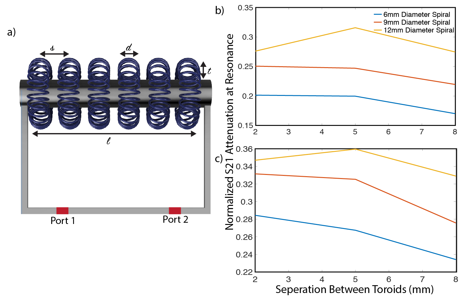
(a) Design is verified by simulations in HFSS, where air-core toroids are placed around a copper rod that is connected to two ports. In order to find the optimal combination of parameters, structure is tested with various separations between toroids ($$$s$$$) and toroid diameters ($$$d$$$) with constant thickness($$$t$$$) and wire diameter. S21 results, normalized by structure length ($$$l$$$) for 12 turn (b) and 24 turn (c) toroids are displayed.
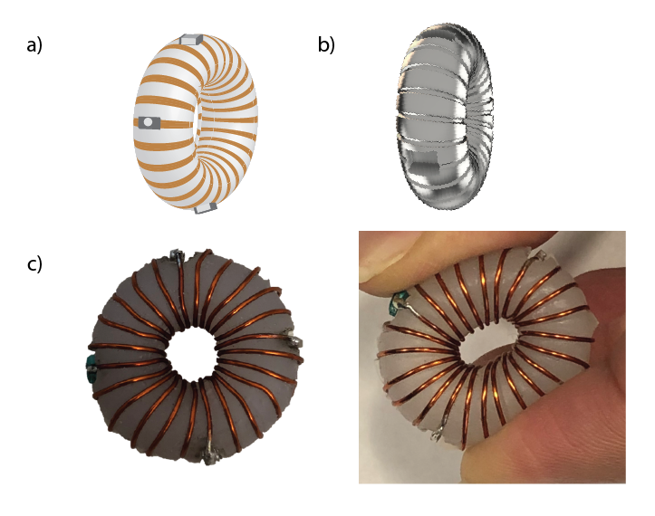
(a) Each trap consists
of a toroidal structure with four tuning capacitors spread evenly (one
variable, 8pF-30pF, and three regular, 4.7pF, surface mount capacitors). (b) A mold is created with a slit to hold the
wire (0.4 mm thickness) and four slots for capacitors. (c)
Final structure is created with an elastic PDMS substrate using injection
molding. Due to the elasticity, the toroid maintains shape after force is
removed.
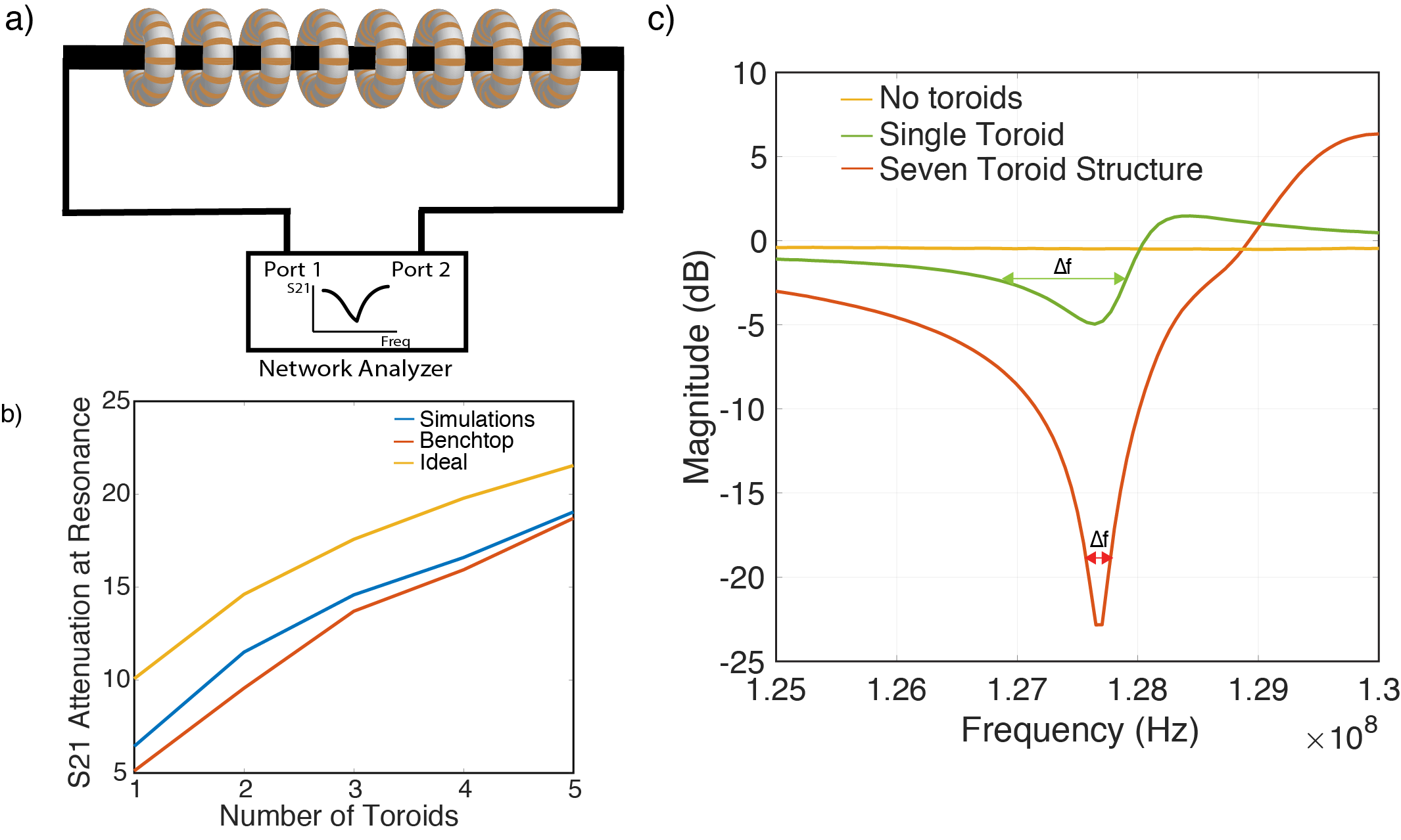
(a) Benchtop
measurements are conducted by connecting the shield of the cable to two ports
of the network analyzer. (b) The S21 attenuation attained at resonance with
different numbers of toroids is measured and compared to results from
simulations and ideal theoretical calculations that assume low loss wires and vacuum
medium, and no interactions between toroids. (c) The S21 curve for a structure
with a single and a 7 toroid structure is shown and the full width at half
maximum is marked.
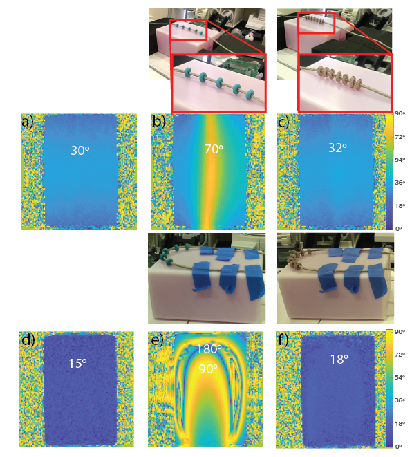
B1 measurement
experiments. Top-middle: A resonant-length
dipole wire is placed on a phantom with spacers. Top-right: with wire
equipped with a 7-toroid caterpillar trap. Second row: B1 maps of a
phantom targeting 30 degree excitation, mapped in range 0-90 degrees. (a)
phantom only (b) with a resonant-length dipole (c) by placing traps we achieve almost
complete suppression of the shield currents. (d-f) show repeated experiment
with a bent structure and targeting 15 degree excitation.