4049
RF field extension and improvement by using floating strip conductors for parallel microstrip coil for PET/MRI insert1Advance Nuclear Medicine Sciences, National Institute of Radiological Sciences (NIRS-QST), Chiba, Japan, 2Molecular Imaging and Theranostics, National Institute of Radiological Sciences (NIRS-QST), Chiba, Japan
Synopsis
For parallel transmit coils, maximum field-intensity is seen for the ROI close to each coil and, peripheral imaging region in between the coils usually show minimum field-intensity. For this reason, a compact orientation of multiple coils is usually used to surround the ROI. An approach of field extension to the regions in between coils is presented here for a 4-channel microstrip coil. Multiple narrow floating copper strips (width 4 mm) were used in between coils. For three such strips, image signal intensity between the coils almost doubled, that resulted in 20% increase in image homogeneity and 25% increase in SNR.
Introduction
In an attempt to develop PET insert for ultra-high field (UHF) (e.g., 7 T) MRI system, we previously developed a prototype 4-channel microstrip transmission line RF coil [1] that included the RF shield box of PET detector modules as the ground conductor of the coil and tested the coil with our available 3T MRI system. To cover the whole imaging region of diameter 150 mm, we needed four extra coils (total 8-channel), that could not be developed due to budget limitation. In that study, it was clear that the peripheral imaging region in between coils had minimum and very low image intensities (also can be seen in the Result section of this summary). To improve image intensities in between coils of the 4-channel coil, in this study, we used parallel extra floating strip conductors on both side of the coils to extend the RF field from the coils to the regions in between the coils. The extra strips acted as antennas that induced and directs the RF field from the microstrip coil to farther imaging regions. This approach may find similarities with the functions of directors used to further extend the field in the famous Yagi-Uda antenna, although no mathematical formulation was used for the positioning of the strips. We did experimental study in the same 3T clinical MRI system with a homogenous phantom.Materials and Methods
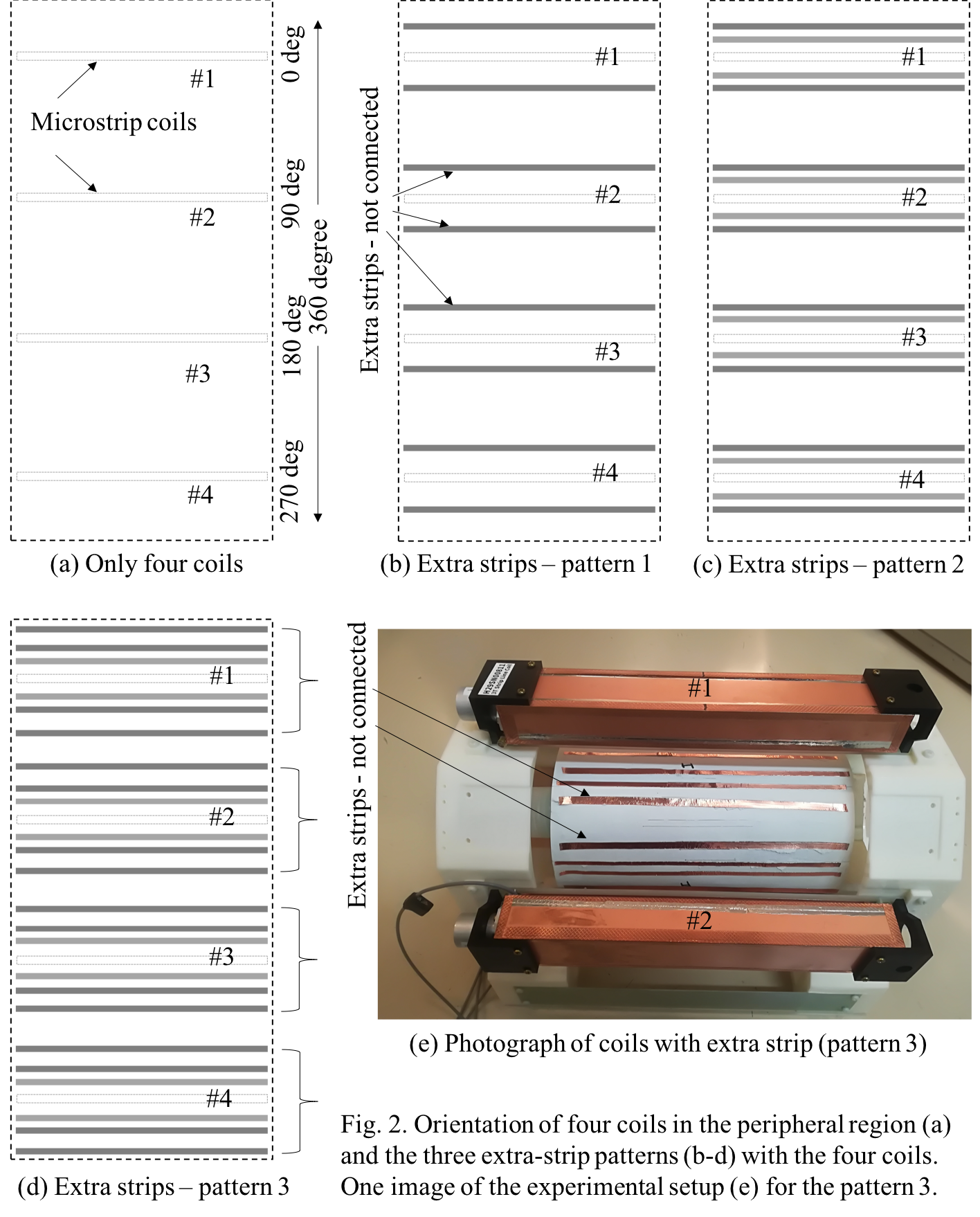
The microstrip coils were previously developed using 35 mm copper PCB. Each coil was 250 mm long (Fig. 1(a)) that was constructed with a 10 mm wide microstrip conductor and a 40 mm wide RF shield box (height of 30 mm) that was used as the ground conductor of the coil. The extra floating strips were made of 35 mm thick copper tape. Fig. 1(b) schematically illustrates the field induction from the microstrip coil and extension to farther regions by extra floating strip conductors. The radial gap between the microstrip conductor and extra strips was about 20 mm. Three patterns of extra strips were studied (Fig. 2): (1) pattern 1 – one extra strip positioning close to each outer boundary of the shield box; (2) pattern 2 – with pattern 1, one extra strips in between the coil center and the first strip; and (3) pattern 3 – with pattern 2, one extra strip outside the 40 mm wide shield box regions. Experimental study was conducted in a 3T MRI system (Siemens MAGNETOM Verio) using a homogeneous (NiCl2.6H2O and NaCl solution) cylindrical phantom of dia. 115 mm and length 200 mm. Gradient echo (GE) images were taken for flip-angle = 30 deg, TR = 300 ms, TE = 4 ms, Slice thickness = 5 mm, FOV = 150 mm and image matrix = 128X128. To calculate RF field using double angle method [2], two GE images were taken with flip-angles 30 deg and 60 deg and TR of 3000 ms, with all other parameters as above.Results and Discussion
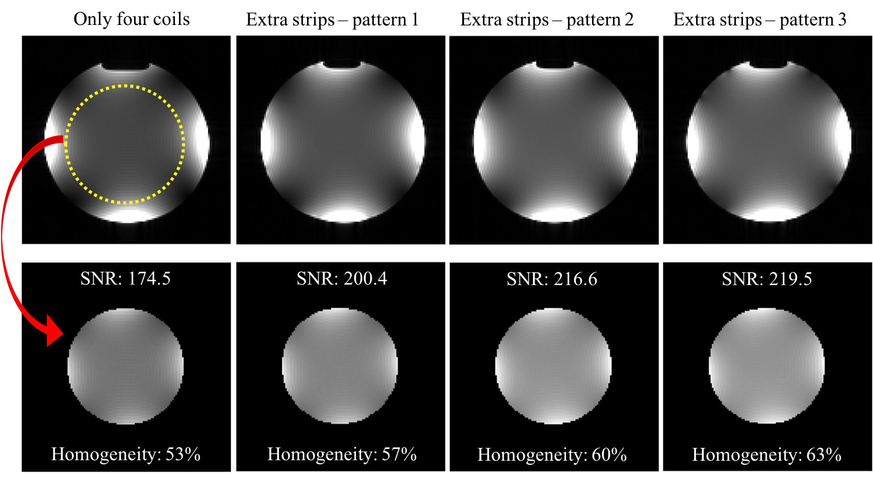
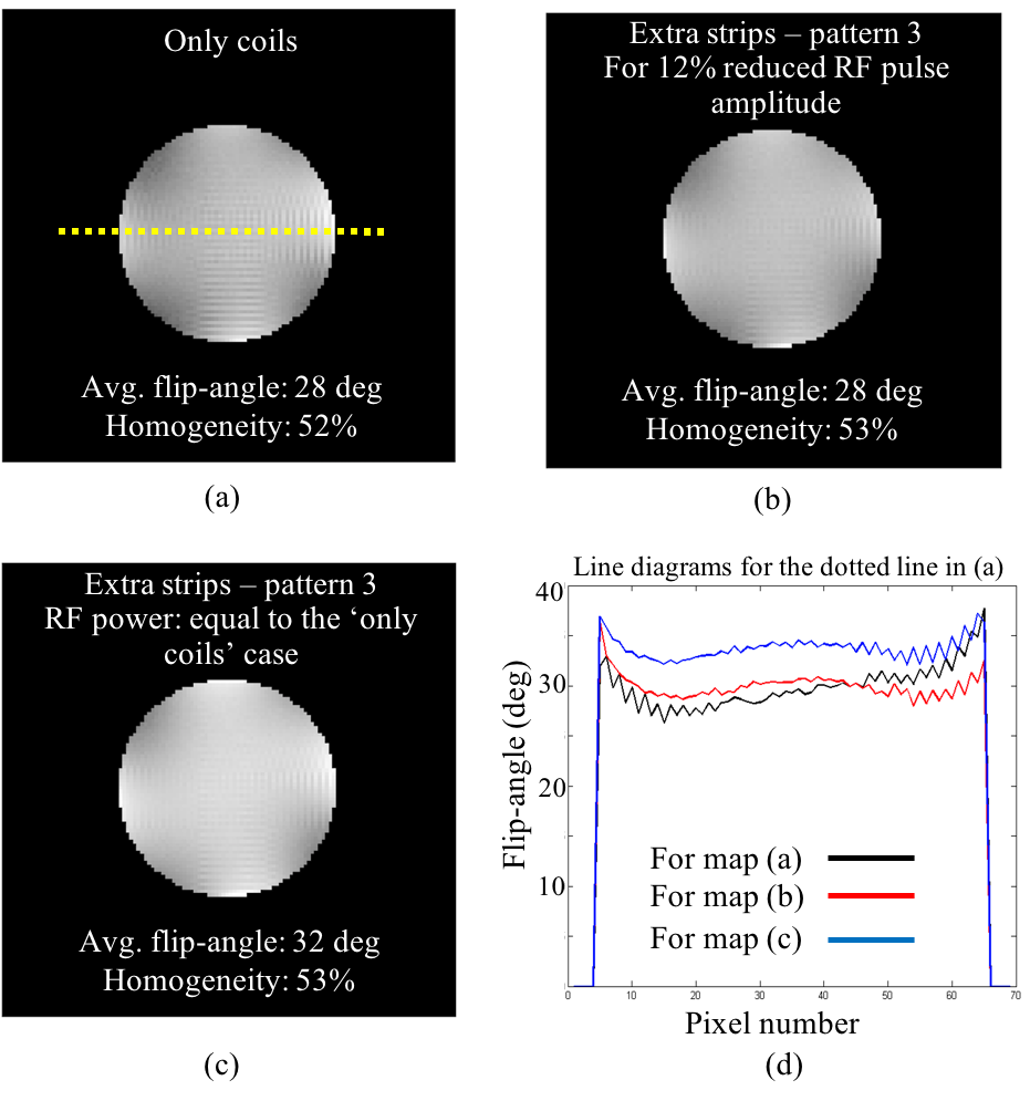
Fig. 3 first row illustrates GE images for the only-coil and the three different patterns of extra strip orientations, respectively. SNR values were calculated for the central approximate 70% ROI and for visual clarity these ROIs are given in the second row of Fig. 3. Signal intensity between coils almost doubled for the pattern 3. The corresponding SNRs [3] and image homogeneities shows maximum increment of respectively 25% and 20% that was achieved for the pattern 3 configuration. Three separate line diagrams are given in Fig 4 with the corresponding lines marked in Fig. 4(a). From the all three line diagrams, it is clearly seen that the signal intensity increased for the whole imaging region for any of the three extra strip patterns. Fig. 5 illustrates the RF transmit field responses. Compared to the only coil case, reduced RF power was required to get similar flip-angle response for the case of extra strips, whereas for equal power to the only coil case, flip-angle values increased. Use of more than three extra strips did not show significant improvement for this case.Conclusion
This study is a pilot study towards a preliminary confirmation of this approach. However, further detail study including simulation would be required. With this approach we expect that a reduction in transmit channels, for example, 12 or a smaller number of channels instead of 16 channels for the case of brain imaging with parallel transmit microstrip coil would be possible. Using dielectric materials in between coils might work similarly, but not good for PET, as it would attenuate the gamma photons.Acknowledgements
No acknowledgement found.References
[1] M.S.H. Akram et al. Microstrip transmission-line array coil dedicated for PET insert for MRI system, Conference record, IEEE-NSS-MIC 2018.
[2] E. K. Insko, et al, J. Magn. Reson. Series A, 103, 82-85 (1993). L. Kaufman, et al, Radiology 173, 265-267 (1989).
[3] L. Kaufman, et al, Radiology 173, 265-267 (1989).
Figures