4046
The feasibility study about the open RF loop & the simple RF circuit topology
Seunghoon Ha1 and Adam Morris1
1Philips Healthcare, Pewaukee, WI, United States
1Philips Healthcare, Pewaukee, WI, United States
Synopsis
It is introduced that the open loop coil with the simple and efficient RF circuit topology with the identical or better coil performance nevertheless less RF components usage. It is analyzed and measured to prove this proposal. It is
compared to the conventional loop coil by thermal test and Q-measurements.
Introduction
A typical receive RF coil is constructed by employing a matching circuit, a balun, a phased shifter, and LNA in series on a tuned parallel LC loop (Figure 1a). This well-known topology has used on the most of conventional coils or research coils. However, it has been re-considerable by the demand of a compact sized feed PCB according to high account array coil introduction. It would be representative that the split coaxial circular loop and RF circuitry were used for the air coil.1 For this intended use, we introduce a new topology with same or better coil performance nevertheless less RF components usage on the segmented loop coil, shown at Figure 1b.Method
From LC series resonance circuit, we can simply derive RL, the series resistance of inductor, with zero phase from the below equation. RL is generally much lower (of the order of 1Ω) since the typical Q of inductor is about 100~200. It can be proven with a single end coaxial cable by S11 network measurement as well.$$Z = \frac{V}{I} = \frac{V}{V/(j\omega L -j\frac{1}{\omega C} + R_{L})} = j\omega L -j\frac{1}{\omega C} + R_{L} = R_{L}$$
From our perspective, it inspires for us to make simpler and more efficient RF coil circuit topology than the typical method. To demonstrate this proposed topology, we build the four segmented rectangular (4inch x 5inch, 0.2inch copper tracer width) loop coil tuned at 1.5T, cut the middle of copper trace, and leave it as the open circuit. As the circuitry to carry on this open loop coil till LNA, the lattice balun is introduced which has various capabilities beside the balun function. After measuring impedance and phase from the open loop coil, LC components values of the lattice balun are calculated and measured for 50ohm impedance matching and 90° phase shift. To activate the transmitter decoupling circuit (TDC), a shunt PIN diode is added at the cross over the balun. A thermal test and Q-measurement are performed to evaluate this proposed loop coil topology after assembling coills. For the thermal test, the two referred shape receiver coils, with the proposed and the conventional RF coil topology each, are placed at 5cm away from 1.5T Philips Achieva transmitter coil wall on the MR bore isocenter. It is assumed that the coil location is in worst case conditions during normal use. TDCs on both coils are passively operated under 21uT, fully maximum system allowance, RF power transmission with 600Hz cycle during 30minutes. Q-factors of these coils are estimated while a conductive phantom is loaded/unloaded on the coil assemblies.
Results
As the expectation, the open resonance loop coil indicated the low impedance without/with phantom loading (Figure 2(a-b)). The lattice balun on the loop made it complete as the fully operational receiver coil, which was well shown at Figure 2(c-d). The activated shunt PIN diode let the loop coil be decoupled completely from the resonance frequency as in Figure 2(e). The temperature deposited on the lattice balun components was 6.4°C degree higher than the conventional circuit topology (Figure 3(b-c)). It was 9.1°C down on the components when the extra two TDCs were added on the open resonance loop coil (Figure 3d). The proposed topology showed negligible Q-factor drop (1.7%) from the resonance loop. To the contrary, Q-factor & ratio of the conventional RF coil circuit topology was degraded inevitably by usage of successive components. The proposed topology had 30.9% higher Q and 3.3% higher expected SNR than the conventional RF coil circuit topology. Even, it was competitive although two extra TDCs were added on the coil as shown in Figure 4.Discussion/Conclusion
We successfully introduced the open resonance loop coil with the simple and more efficient RF circuit topology instead of usage of several successive components for the conventional RF coil assembly. At the thermal test, the proposed concept generated more heat than the other due to low blocking impedance of LC components on the lattice balun. But, it is still valuable since the maximum allowed temperature on the coil surface on human contact, not the components, is 41°C in accordance with IEC60601-1.2 While adding two TDCs on the proposed, the temperature is drastically down and Q-factor was still competitive, comparing to the conventional RF loop coil. This concept is also useful to build a high impedance RF array coil to minimize mutual coupling owing to easy impedance conversion by the lattice balun.3 It is anticipated that it will be suitable on the high account array coil integration.Acknowledgements
Thanks to Paul Koronkowski for making the prototype circuit PCB.References
1. C.Stack et al., US patent, US20190154775A1, 2019.
2. IEC60601-1, 3rd edition, 2005-12
3. B. Zhang et al., Nature Biomedical Engineering 2, 570-577, 2018.
Figures
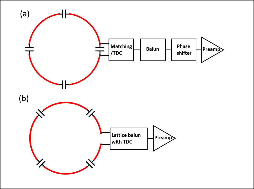
Figure
1 : The block diagram for two circuit topologies on the receiver loop coils;
(a) the conventional circuit topology and (b) the proposed concept.
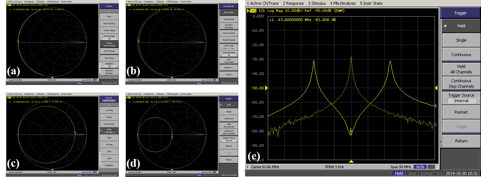
Figure
2 : The network measurements for the open loop coil; The impedance of the open
loop coil without (a) and with (b) loading a conductive phantom. The impedance
and phase change without (c) and with (d) loading a conductive phantom
while implementing the lattice balun on the open loop coil. The
frequency response under activated PIN diodes (e).
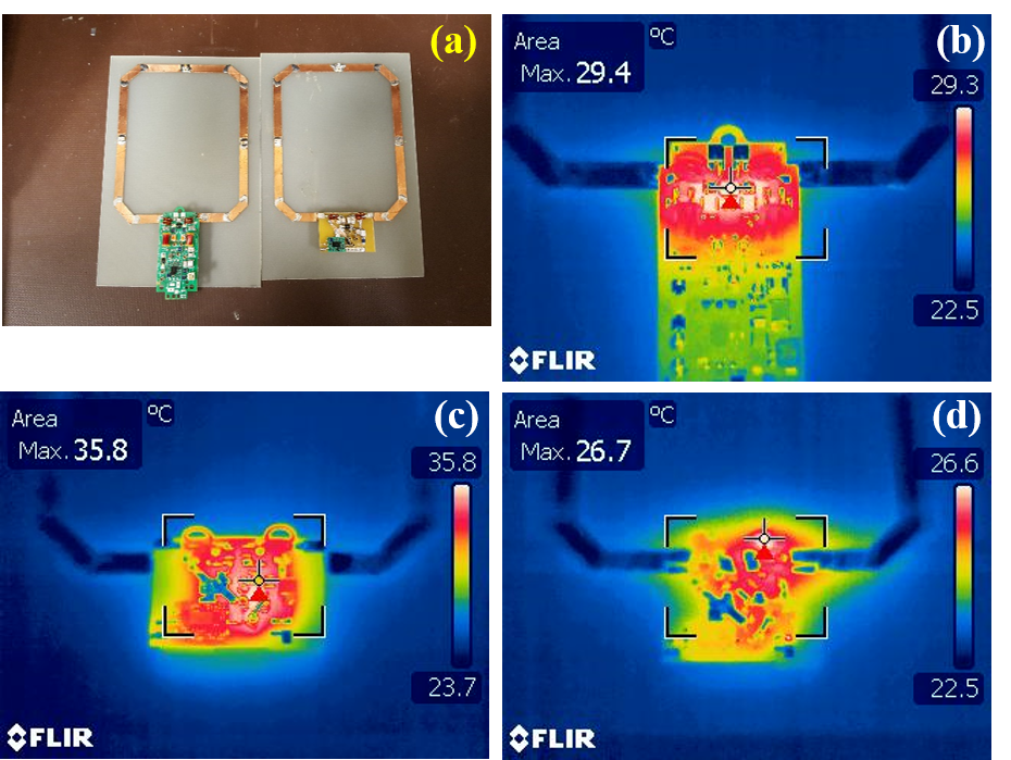
Figure
3 : (a) The loop coils are arranged with two loop coil topologies. The left is
used with the conventional RF coil topology and the other is done with the
proposed concept. (b-d) the captured temperatures on the exposed components of
loop coils under Tx coil transmission; the
conventional loop circuit topology (b), the proposed concept (c), and the
proposed concept with extra TDCs addition (d).
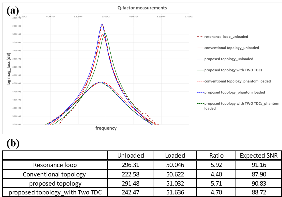
Figure 4 : frequency response plots
(a) and the Q measurements and Expected SNR (b) according to coil assemblies