4045
Optimized Quadrature Head Coil Improves SNR in the Brain at 6.5mT1Department of Radiology, A.A Martinos Center for Biomedical Imaging/MGH, Charlestown, MA, United States, 2Harvard Medical School, Boston, MA, United States, 3Department of Physics, Harvard University, Cambridge, MA, United States, 4State Key laboratory for Power Transmission Equipment and System Security and New Technology, Chongqing University, Chongqing, China, 5Institute of Imaging Science, Vanderbilt University, Nashville, TN, United States
Synopsis
High performance RF coil design is challenging at ultra-low field as rules of thumb learned from high-field may not apply. Previously, we built a 2-channel quadrature head coil with orthogonal B1 fields using an air-core transformer to null the mutual coupling between the coil, however this was unsuccessful in boosting the SNR beyond that of our single-channel spiral volume coil for brain imaging at 276 kHz. Here, a new optimized quadrature coil with a capacitive decoupling element and a new outer layer coil was designed. Images acquired show an expected √2-factor or more enhancement in combined maximum SNR.
Introduction
In the ultra-low field regime, the noise floor in RF coils is dominated by Johnson noise. High-performance RF coil design at 6.5mT presents unique engineering challenges which sometimes are not well advised by work done at high-field. Our previous coils focused on a one-channel spiral head coil1 with maximum coverage of the volume of interest and a 2-channel quadrature head coil2 which had the goal of increasing the SNR by √2 3. So far, our 1-channel coil has enabled 3D proton-density weighted brain images of 2.5 × 3.5 × 8.5 mm3 spatial resolution, acquired in 6 minutes (NA=30)1,4. As for the quadrature coil, our previous results showed more 30% more noise in one of the channels, with no net increase in SNR compared to the 1-channel coil. Here we describe an optimized transmit/receive quadrature head coil (Figure 1). Our goal is to improve the SNR, thus allowing less averaging to be performed and shortening scan time. To evaluate the performance of the quadrature coil, both phantom and in vivo brain images were acquired, and the results were compared with the one-channel coil.Materials and Methods
Coil description: As in the previous work2, the same quadrature helmet made up of two nesting layers was used. The inner was not modified and consisted of 30 spiral turns with a B1 field in the axial (x)-direction. The outer layer coil was rewound into a biplanar configuration with 29 orthogonal loops and a resultant B1 field in the anterior-posterior (y)-direction (Figure 1). Both B1 fields are orthogonal to the B0 z-axis.In this optimized quadrature coil, the two layers were first assembled together. Incomplete geometric decoupling resulted in some inductive coupling between the channels. Here, instead of the air-core transformer as used previously a capacitive decoupling element (Cd) was added in the circuit (Figure 1 A and B). Hence both the tuning/matching and decoupling were performed all at once. To null this mutual coupling, the capacitive decoupling method was preferred because the transformer was very position sensitive thus unstable and resulting in constant tuning/matching. The outer layer and inner layer were tuned at 276.2 kHz and matched to at least -35 dB (S11/S22 parameter), and both coils were geometrically decoupled by –23 dB (S12 parameter).
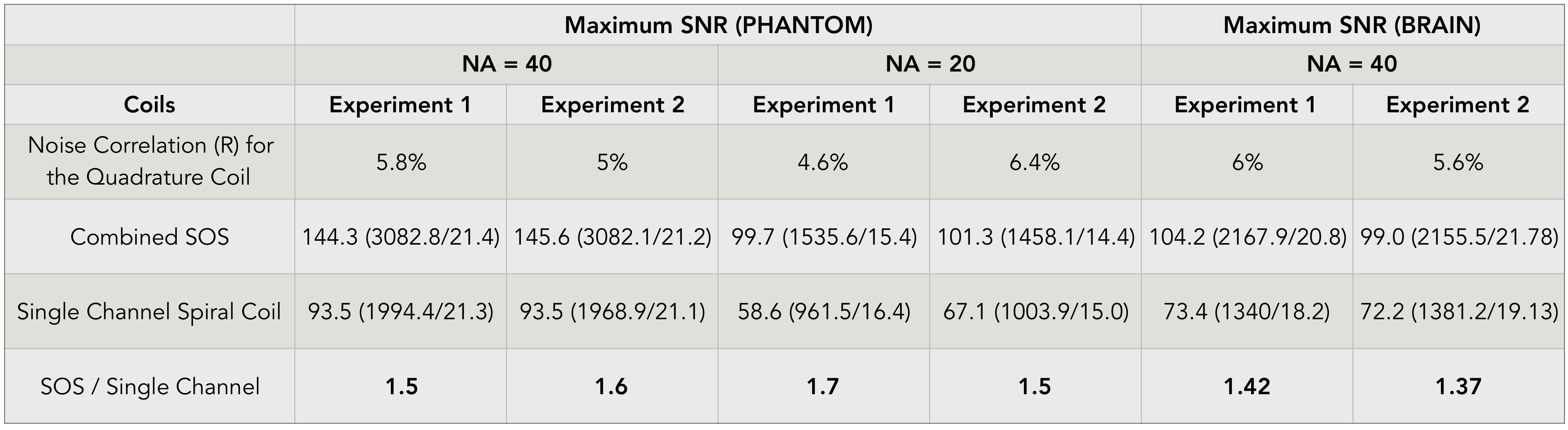
Imaging: A water-filled structured phantom3 was placed inside the coil. The quadrature head coil was placed in our ULF MRI scanner, with the inner coil was connected to the active T/R switch and the outer coil directly to a second receiver channel. A 3D b-SSFP sequence was used with 50% undersampling ratio, matrix size of 75×64×15, voxel size of 2.5×3.5×8.5 mm3, the number of averages of 40 and the scan time was 8.5 minutes. The performance of the quadrature coil was compared to that of the one-channel spiral coil. All the imaging parameters, the receiver gain and shim set values were kept constant. This same experiment was also performed in vivo on the brain. All experiments were duplicated. Noise correlation for the two-channel array are calculated using noise vectors acquired by the loaded coil with the transmit RF voltage set to zero (Figure 5).
Data Analysis: Raw data was reconstructed with the sum of squares (SOS) method from both channels and compared to the previous single-channel spiral head coil. The maximum SNR and mean SNR were calculated by taking either the maximum signal or the mean signal over the ROI of the phantom/brain and dividing it with the standard deviation (std) of noise in a specified region-of-interest (ROI).
Results
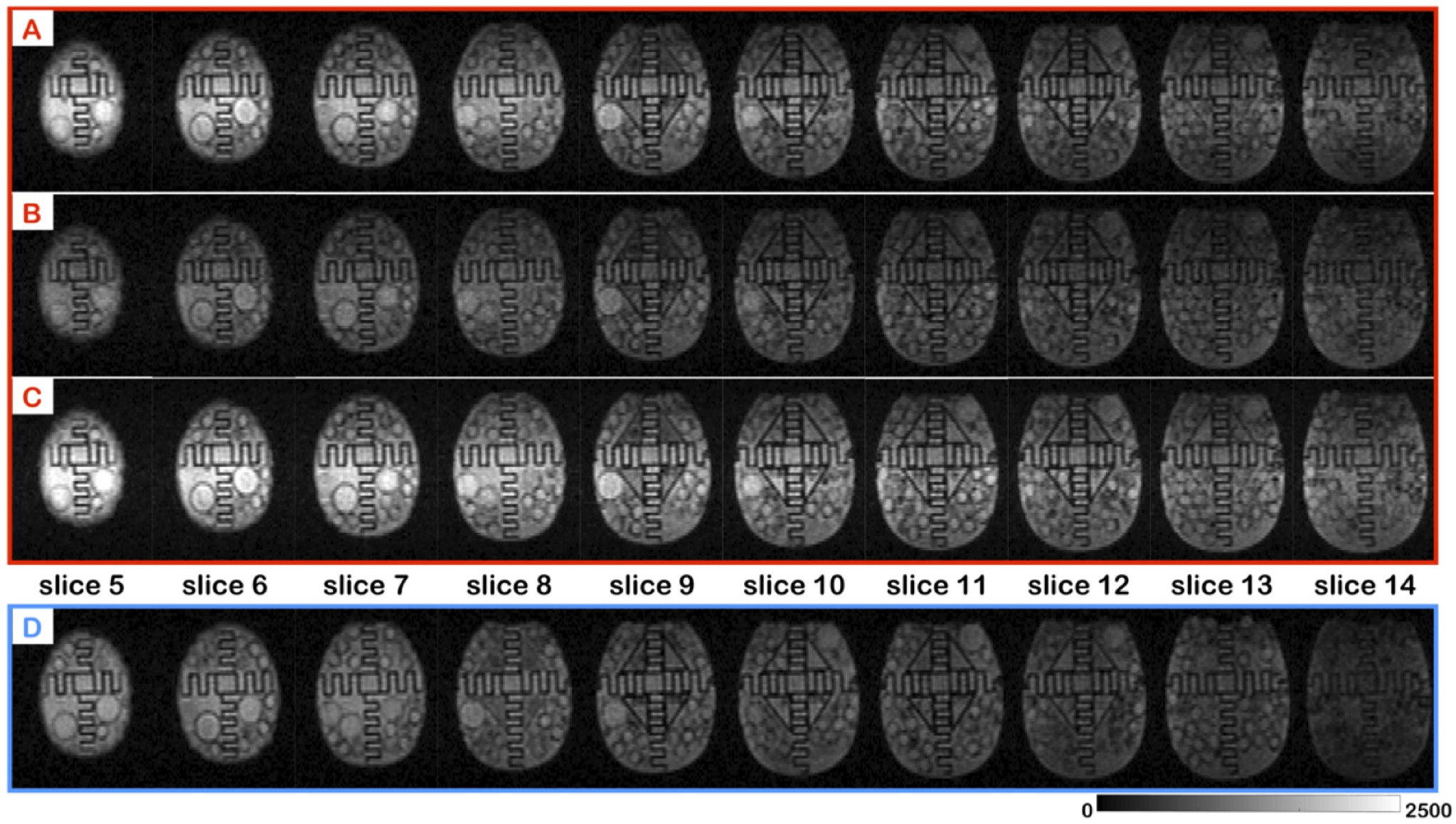
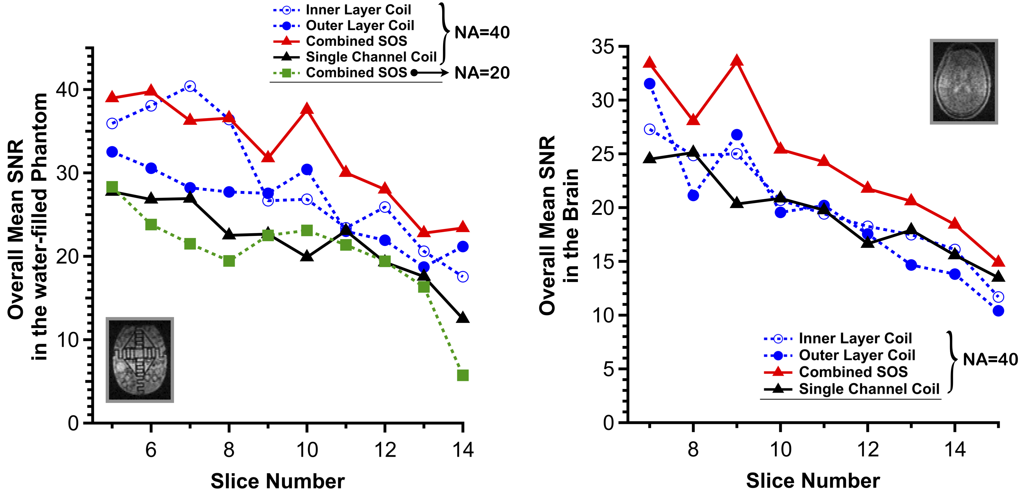
Figure 2 and Figure 4A show the images obtained from the phantom experiment with the corresponding SNR values. The images acquired with the quadrature coil have more contrast than the single channel coil. We observe that the center part of all the slices is brighter for the inner layer coil probably due to a higher Q coil, which can be lowered by adding a resistor. (Note: the slices acquired with quadrature coil are not an identical match to that of the single channel coil). The SNR evaluated across the slices for the quadrature coil shows a significant increase the SNR. The maximum SNR of the quadrature coil was of 144.3 versus 93.5 for the one-channel coil. Data was also acquired with NA=20 with the quadrature coil and the maximum SNR was evaluated to 99.7, showing that with half the scan time the same SNR can be achieved as with the single channel coil. For the in vivo brain experiment, similar results were obtained in Figure 3 and its corresponding SNR analysis in Figure 4B. Images obtained with the quadrature coil were brighter and the maximum SNR enhancement was of 1.42 when compared to the one channel coil.Discussion and Conclusion
An increase in the maximum SNR of 40% was observed in vivo with the quadrature coil as compared to the one-channel coil. Noise correlation values of around 5% was obtained, showing minimal coupling between channels. The phase images of each channel were out of phase with each other, showing that the 2 layers were geometrically decoupled. Conclusion: We have demonstrated an optimized quadrature head coil for use at ULF that will allow us to accelerate overall imaging.Acknowledgements
No acknowledgement found.References
1. ‘A single channel spiral volume coil for in vivo imaging of the whole human brain at 6.5 mT’, C. D. LaPierre, M. Sarracanie, D. E. J. Waddington and M. S. Rosen, ISMRM abstract Proc. Intl. Soc. Mag. Reson. Med. 23 (2015) 5902
2. ‘Quadrature Head Coil for Brain Imaging at 6.5 mT’, N. Koonjoo, B. Primavera, J.P Stockmann, T. Witzel, L.L Wald and M. S. Rosen, ISMRM abstract Proc. Intl. Soc. Mag. Reson. Med. 25 (2017) 2664
3. ‘Quadrature detection in the laboratory frame’, D. I. Hoult, C.-N. Chen, V. J. Sank, Magnetic Resonance in Medicine 1 339–353 (1984)
4. ‘Low-Cost High-Performance MRI’, M. Sarracanie, C. D. LaPierre, N. Salameh, D. E. J. Waddington, T. Witzel and M. S. Rosen, Scientific Reports 5 15177 (2015)
Figures
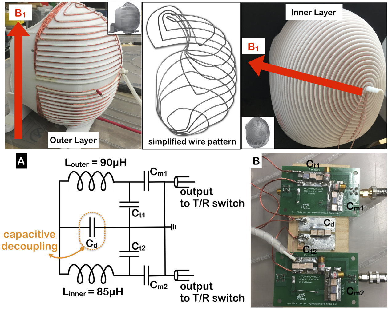
Top Panel - Photographs of quadrature head coil. An outer layer coil (left) with a vertical B1 surrounds an inner layer coil (right) with a horizontal B1. The diagram (middle) is a simplified version of the outer layer wire pattern. Inset figures show CAD rendering of each layer. Bottom Panel - A - Schematic representation of the circuit board – (up) the outer layer coil (down) outer layer coil. A capacitive decoupling element (enclosed rectangle) was used to null the mutual inductance. B- Photograph of the real circuit board with the corresponding labels of the tune and match components.