4044
Strategies to reduce coupling for continuous acquisition of a Bloch-Siegert spatial encoding in low-field MRI device1Department of Radiology and Biomedical Imaging, Yale University, NEW HAVEN, CT, United States
Synopsis
This work describes methods and systems to implement Bloch-Siegert(BS) spatial encoding using simultaneous transmit and receive in low-field MRI. The key challenge is to reduce coupling power in receiver chains so that the on-resonance signal can be acquired during the off-resonance irradiation. The developments include combining filters and coil decoupling methods. Together these methods suppress irradiation leakage more than 60dB which, for an anticipated offset B1 field of 60 dBm, allows for spatial encoding in low-field MRI device.
Introduction
Recently, there has been interest in low-field MRI devices for applications in point-of-care diagnostics1. Our group is developing an approach that combines a ramp-able and nonuniform electromagnet for polarization and slice selection, as well as RF encoding to replace gradients for in-plane encoding2. This not only eliminates the need for additional gradient amplifiers but also provides silent scanning and elimination of claustrophobia associated with cylindrical magnet geometries. Single point BS encoding3, as a novel RF encoding technique, was developed by Kartäusch for RF fields that generate linear phase modulation. Our group2,4 has been working on BS encoding for arbitrary nonlinear RF fields using an array of coils that would simultaneously irradiate off-resonance and detect signal on-resonance. This approach corresponds to using BS RF pulses like readout gradients, which would increase the time efficiency by orders of magnitude. However, to avoid saturating the preamplifier due to large coupling power on receive channels, special hardware for this NMR/MRI device must be developed. In this work, filters and coil decoupling methods are combined to address this problem and make such a system feasible.Methods
The open MRI system (Figure 1) was built, including electromagnet, a copper shield layer, a volume coil and a 3x3 array coil. For spatial encoding that uses BS shift, a subset of coils in the array generate encoding patterns across the slice by playing off-resonance pulses at 870kHz, while other coils in the array simultaneously receive signal on resonance at 1MHz. The coupling parameter S12 between coils is a function of the irradiation and detection frequencies. In experiments using simultaneous transmit and receive, the harmonic components in RF pulses increase coupled voltage on the detection coils when the harmonic components are close to the detection frequency. To reduce these harmonic components, we have built a low-pass filter into the transmit chain (Figure 2). Filters were also used in each receive channel to reduce off-resonance component in signal. Figure 3 is a graph illustrating S12 results of the high-pass ellipse filter (KR Electronics Inc.) which shows steep roll-off characteristics around 870kHz, and the insertion loss is around 0.2db at 1MHz.Filtering efforts alone, may not sufficiently attenuate off-resonance components in the receive path. Appropriate decoupling techniques in the array also must be used. In addition to geometric decoupling, inductive decoupling which is insensitive to frequency was exploited to build the frequency-switchable array coils (Figure 1 and 2). Coupling is adjusted by inductors for adjacent coils, while small loops connected by coaxial cables are used to reduce coupling between coils that do not overlap. These were used to acquire conventional receive signal at Larmor frequency(1MHz) as well as to generate offset fields at 870kHz.
Results
Figure 4 shows the mutual coupling achieved when each coil was tuned and matched to 50 Ohm at 1MHz. However, coupling levels are different when coils are switched to different frequencies. For example, S12 is -40.8 at 1MHz measured by VNA with transmit power 0dBm when coil #7 and coil #1 are on and off resonance (1MHz and 870kHz), respectively. Measurements were taken using the array coil in Fig.2 and a high-pass filter in Fig.3, and those results are summarized in Fig.5. For example, when off-resonance pulses at 870kHz, corresponding to 1kW(60dBm), are applied on coil #7, the coupled power on coil #1 and coil #4 are 6.2dBm and -0.8dBm, respectively. After running through high-pass filter, the residual powers are -26.7dBm and -31.3dBm, which is consistent with the reported filter characteristics in Fig.3. In this way, a low-noise preamplifier(LNA) (Advanced Research Receiver, P0.5-30/20VD) in the first stage, which has the maximum input power 2dBm, would not be saturated, making simultaneous transmit/receive BS spatial encoding possible.Conclusion and Discussion
We present a design for an MRI device using BS nonlinear spatial encoding. It was successfully shown that the strategies combining coil decoupling and filters help to reduce coupling power and remove the off-resonance signal, such that BS encoding radiation can be applied while detecting the on-resonance signal simultaneously. This development allows BS encoding to be applied in the same manner as a readout gradient, thereby increasing the efficiency of this spatial encoding technique by orders of magnitude.Acknowledgements
We would like to thank the help of Terence Nixon and Scott McIntyre.References
[1]Sarty G E and Vidarsson L. Magnetic resonance imaging with RF encoding on curved natural slices. Magnetic resonance imaging. 2018; 46: 47-55.
[2]Constable R T, et al. Design of a novel class of open MRI devices with nonuniform Bo, field cycling, and RF spatial encoding. In: ISMRM.;2019. p. 113.
[3] Kartäusch R, et al. Spatial phase encoding exploiting the Bloch–Siegert shift effect. Magnetic Resonance Materials in Physics Biology and Medicine. 2014; 27(5): 363-371.
[4] Wu B, et al. RF encoding using a simultaneous transmit and receive system. In: ENC.; 2019.
Figures
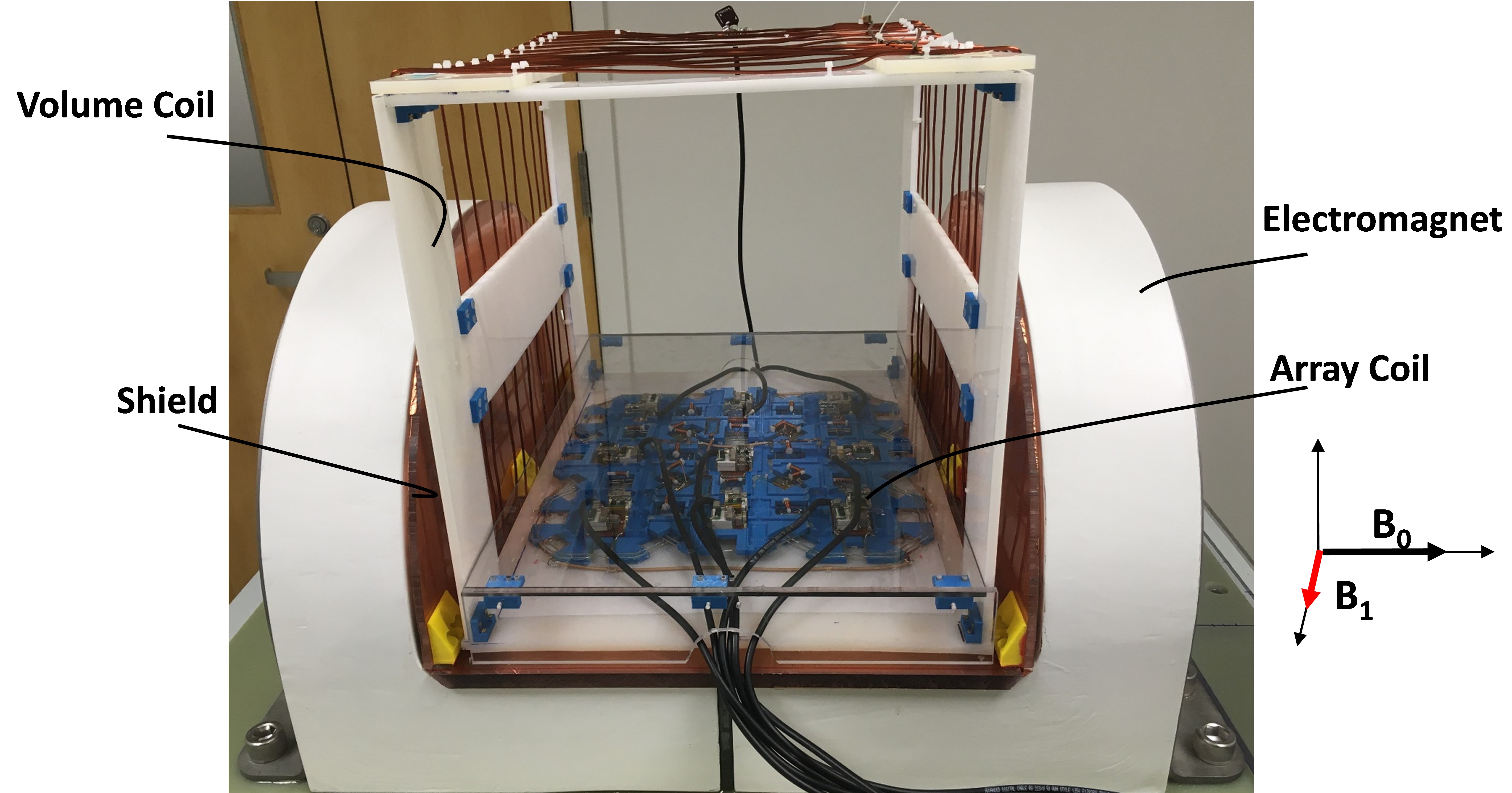
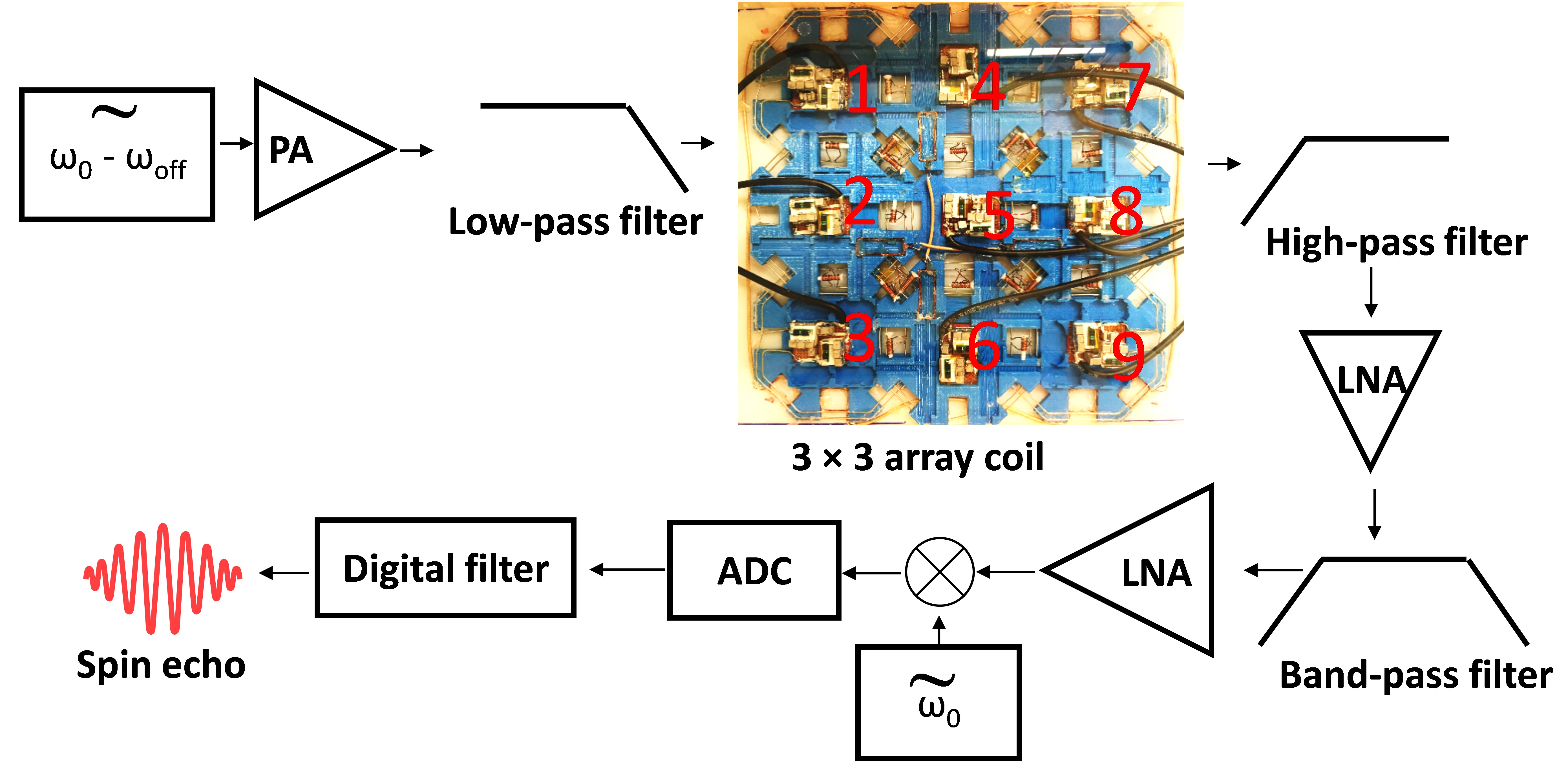
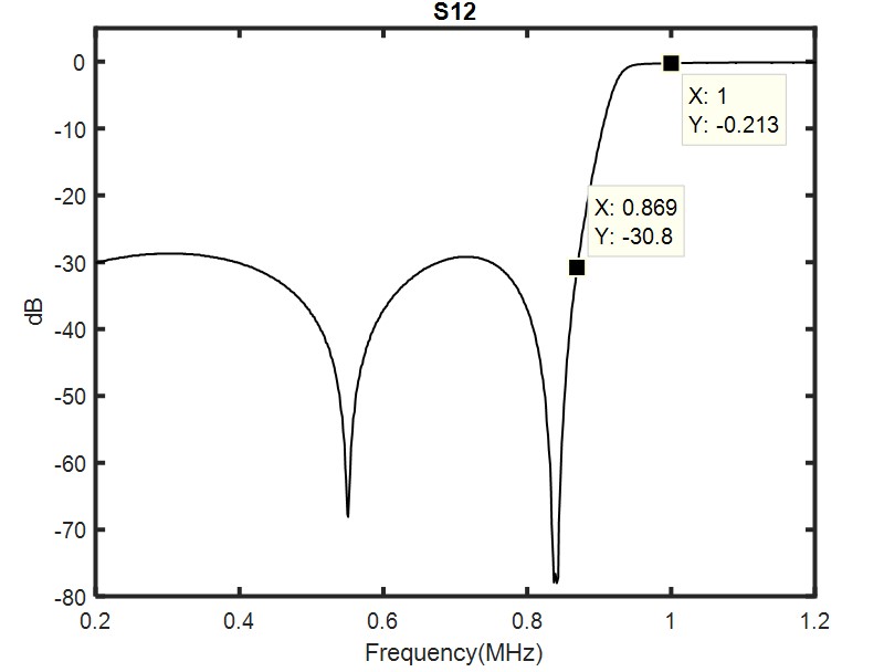
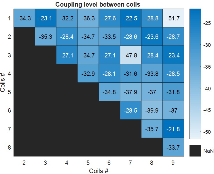
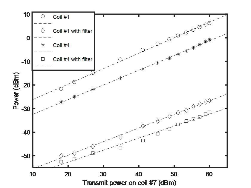
Figure 5: This figure shows relationships between power applied on transmit coil and coupled power on receive channel. For “o” data and “*” data, the coupled power linearly increases as transmit power changes. For “◊” data and “□” data, they are outputs of the high-pass filters.