4043
An automated 32 channel VNA RF switch for high density coil prototyping
Dimitri Welting1, Carel C. van Leeuwen1, Alexander J.E. Raaijmakers1, and Dennis W.J. Klomp1
1Department of Radiology, University Medical Center Utrecht, Utrecht, Netherlands
1Department of Radiology, University Medical Center Utrecht, Utrecht, Netherlands
Synopsis
An automated 32 channel vector network analyzer switch was developed in-house, to be used for high density coil arrays. Using this device full S11 and S21 measurements of 32 channels can be acquired on the bench in less than 2.5 minutes. Performance of the device was evaluated using a 32 channel 7T headcoil and a 8 channel 7T dipole body array.
Introduction
Due to the need for high accelerations, high density coil array designs are now commonplace. However measurement equipment is generally not designed for such high number of ports. The relatively low number of ports on vector network analyzers (VNA) makes bench measurements of the coil interaction slow and error prone due to the need to keep switching the coil connectors on these ports. This study presents an automated 32 channel RF switching device (Figure 1) which increases the total number of ports in a VNA from 2 ports to a virtual 32 ports.Methods
Hardware design:The design of the 32 channel RF switch is centered around low insertion loss RF switches, with a working frequency range encompassing 20 to 3000 MHz to include all commonly used MRI RF frequencies. These RF switches are connected to 50 Ohm coplanar waveguides and striplines to minimize losses. Special care was taken to ensure coupling to neighboring channels was minimal, resulting in a coupling between channels of less than -30 dB. By incorporating a 4-way RF switch in the final stage of the circuit, the input impedance of ports that are not currently measuring can be set to 50 Ohm or to a preamp decoupling impedance. The final stage of the VNA switch is a wideband 50 Ohm matching network to ensure the attached coil is always connected to a 50 Ohm system. Extended features such as the ability to impose DC bias for detuning and malfunction checking are also included to further facilitate the measurement procedure.
The ports of the VNA are connected to the back of the VNA switch. The signal is then led through 3 RF switches to the selected channel on the front of the device. With these RF switches any port combination can be realized, giving it a total of 1024 (322) possible port configurations which can be used in the analysis of the connected coil.
The controlling hardware consists of an ARM cortex m0+ microcontroller. The microcontroller gives the device USB capabilities, to enable the possibility for fully automatic measurements.
The board schematics and PCB files are designed in the KiCad EDA suite (kicad-pcb.org).
Software design:
Software was written in Python 3 to interface with the VNA switch and display measurement data acquired from the VNA. The written software interfaces with a TR1300 2-port VNA (Copper Mountain Technologies, Indianapolis, USA), but can easily be rewritten to encompass other VNA’s capable of interfacing with personal computers.
Validation:
To test the VNA switch performances and accuracy a comparison was performed between traditional manual measurements and the measurements acquired via the device. The available VNA is limited to S11 and S21 measurements; therefore these two types of measurements will need to be validated. S11 measurements were performed on a 32 channel 7T headcoil (Nova Medical, Wilmington, USA) (Figure 2A). S21 validation was performed on an in-house built 8 channel 7T dipole body array1 (Figure 2B), resulting in 64 measurements. Cable traps were added to avoid measurement discrepancies due to cable positioning differences between the manual and automatic measurements.
Results and Discussion
S11 measurements of the 32 channel headcoil are shown in figure 3. Results show good agreement between manual and automatic measurement; on average there is 98.7% accuracy in absolute power on the 7T proton resonance frequency. These differences can be explained by difference in cable positioning, slight differences between 50 Ohm terminators used in the manual measurement and the wide-band 50 Ohm matching performed on the VNA switch.S21 measurements of the 8 channel dipole body array are shown in figure 4. Results show good agreement; on average there is 99.7% accuracy in absolute power on the 7T proton resonance frequency. However, an unexpected resonance peak can be seen on multiple channels during the automatic measurement (Figure 4D). This resonance peak can occur even without any coils attached to the VNA switch, which indicate improper decoupling of the channels on VNA switch PCB boards causing a resonant loop to be formed. Due to the lower power of the measurements the distortions caused by these resonant peaks do not have a big impact on the accuracy.
S21 coupling matrices of the two measured setups are shown in figure 5. Figure 5 A and B show matrices generated from the automatic measurements, while figure 5C shows the coupling matrix generated from the manual measurement.
Large measurements consisting of 1024 individual measurements can be performed in approximately 2.5 minutes, using 501 data points per measurement. Reducing the amount of points to the minimum for single frequency measurements can reduce this time to approximately 30 seconds.
Conclusion
A 32 channel vector network analyzer switch was built to facilitate measuring high density coil arrays on the bench. With the 32 channel switch and corresponding software full 32 channel S-parameter matrices can be acquired in as few as 30 seconds (one frequency) or 2.5 minutes (501 frequency points). Verification and characterization of transmit and/or receive coil arrays is now sped up considerably. However, minor spurious resonances exist in the current device, which cause erroneous dips in low-magnitude S-parameter curves.Acknowledgements
No acknowledgement found.References
1. Raaijmakers et al. The fractionated dipole antenna: A new antenna for body imaging at 7 Tesla. Magnetic Resonance in Medicine; 2015Figures
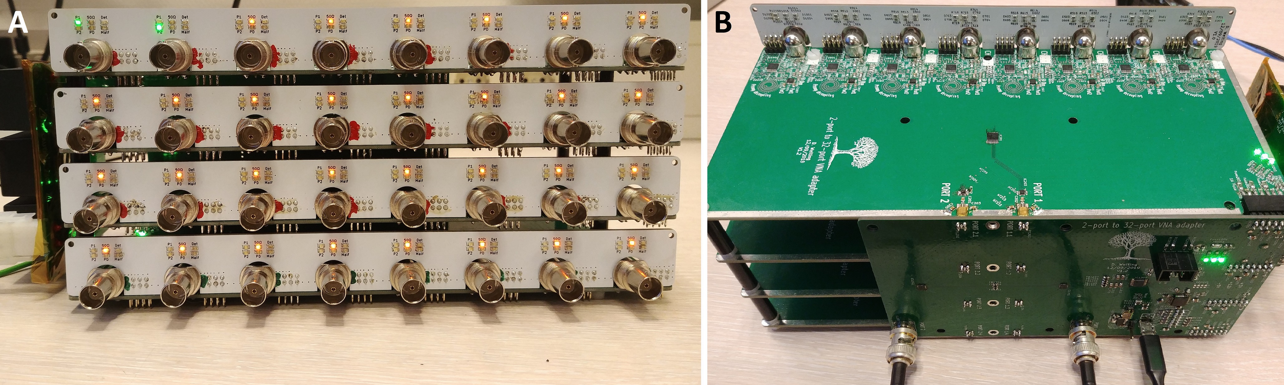
The
front of the device (A) consists of 32 BNC connectors and several LEDs showing
the current configuration. The ports of the VNA and a USB cable can be attached
to the back of the device (B).
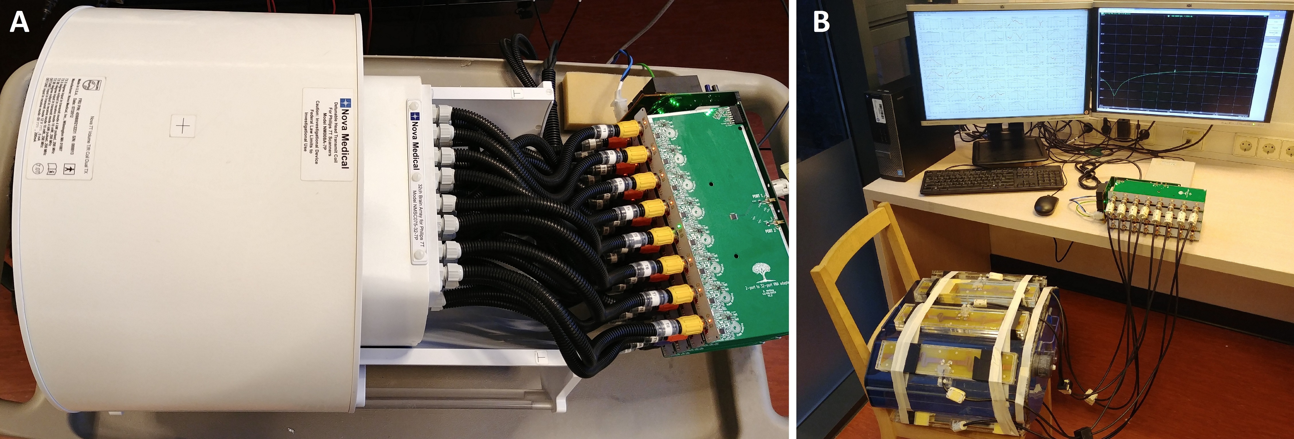
Two
coil setups were measured with the VNA switch. (A) Shows a 32 channel 7T
headcoil attached to the custom vector network analyzer switch. (B) Shows an 8
channel dipole array around a 3g/L NaCl body phantom.
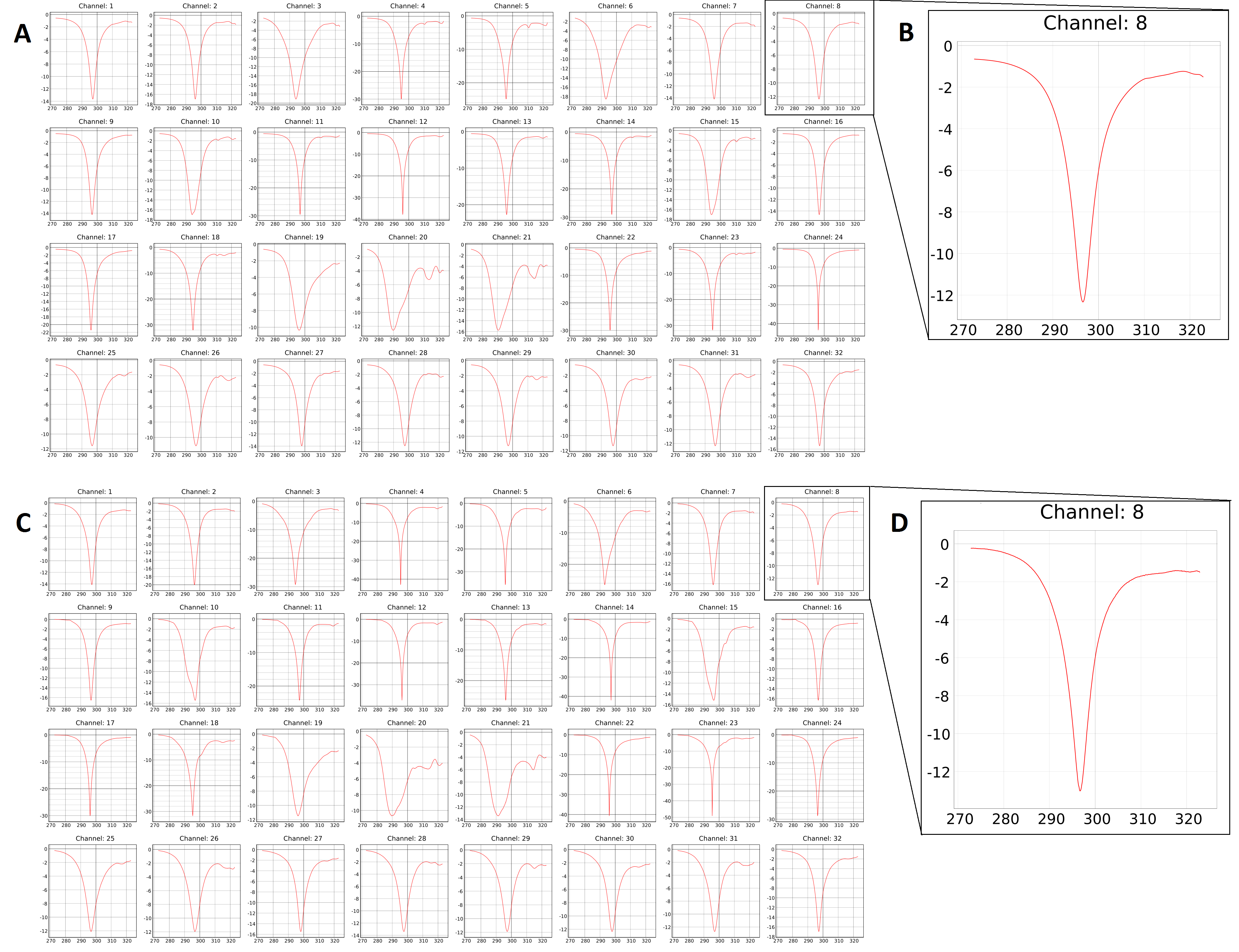
Two
32 channel S11 measurements were performed. A manual measurement (A) was performed
using 50 Ohm terminators and extensive connector switching. Using the VNA
switch an automatic measurement (C) was performed using the same setup. (B, D) Detailed
views. All axes are in dB (vertical) and MHz (horizontal).
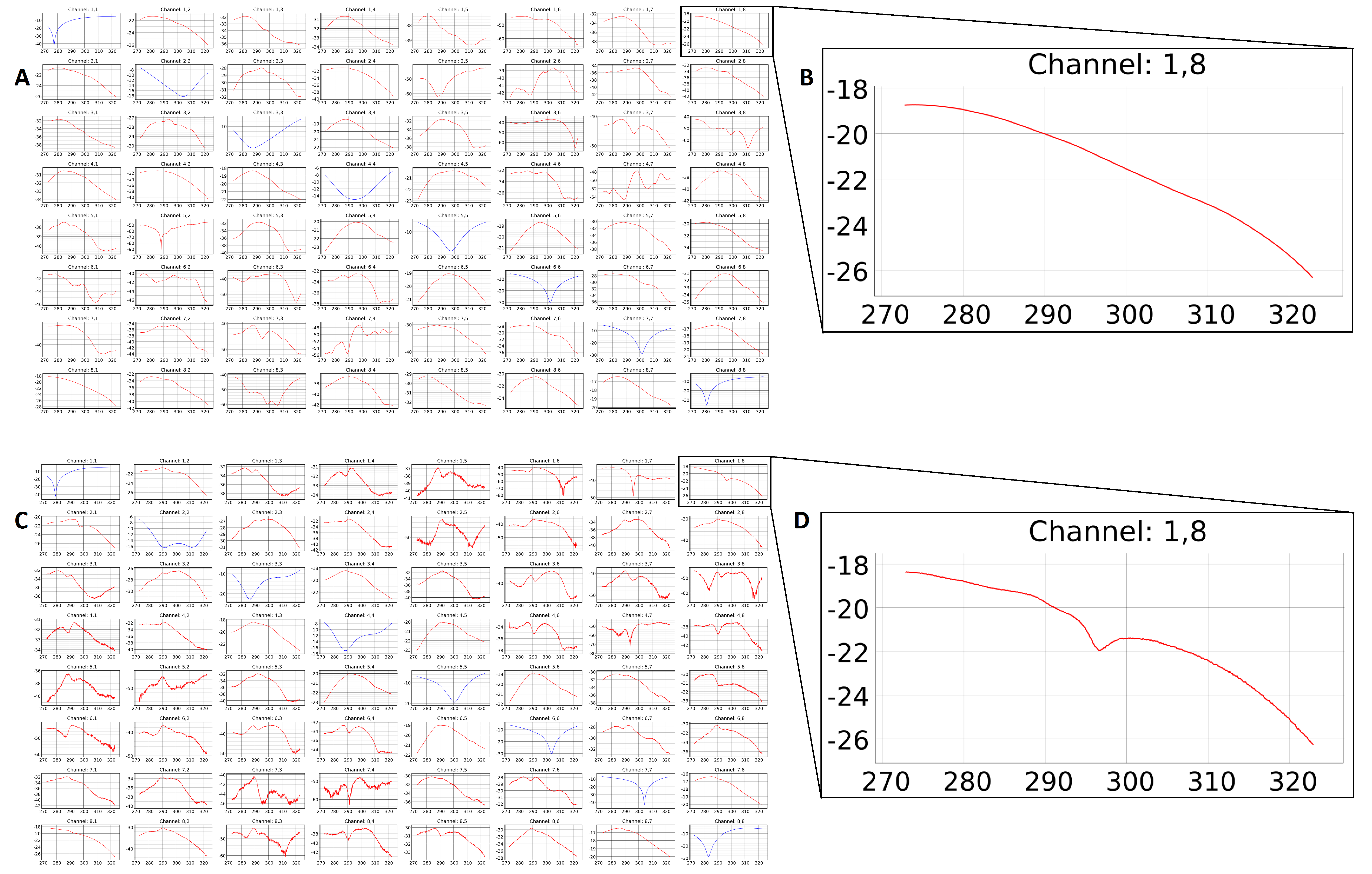
Two
8 channel S21 measurements were performed, resulting in 64 individual
measurements. (A) Manual measurement
(C) automatic measurement. S11 measurements are visible in the diagonal line
(top left to bottom right). (B, D) Detailed views. All axes are in dB
(vertical) and MHz (horizontal).
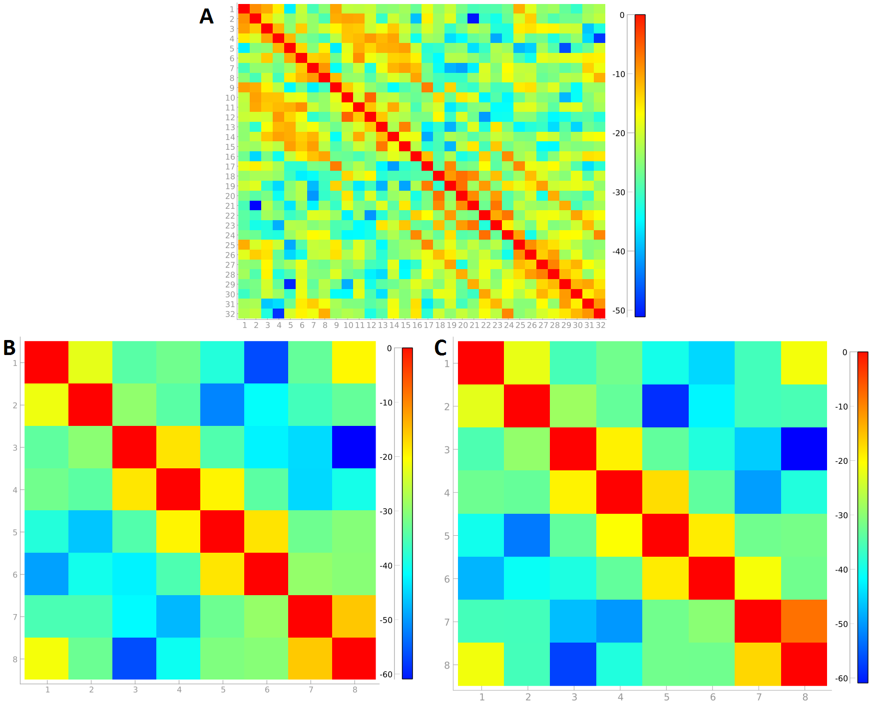
Automatic
measurements allow for big coupling matrices generated on the bench. 32 channel
(A) and 8 channel (B) matrices derived from the two coil setups are shown. (C) Shows an 8 channel matrix derived from
manual measurements. The colors
correspond to the measured S-parameter in dB.