4042
Optimization and miniaturization of Rx-only coaxial coil interfacing.1Division MR Physics, Medical University of Vienna, Vienna, Austria, 2IR4M, Université Paris-Saclay, Orsay, France, 3Université de Lorraine, Nancy, France
Synopsis
Coaxial coils have been introduced recently, the way of interfacing these coils impacts the achievable SNR. In this work, the interfacing circuitry is studied to optimize sensitivity and ensure safety. Performance tests on the bench and in the MR scanner were done for 8-cm 123 MHz coaxial coils, operated at their self-resonance. It was found that a high inductance across the port and symmetric matching capacitors increase SNR. A balun and a phase shifter for preamp decoupling are described, the correct positioning of a fuse is demonstrated. Miniature preamplifiers and toroid inductors minimize size and weight to obtain maximum flexibility.
Introduction
Radiofrequency coils made from coaxial cable were recently introduced1,2. The cable’s inner and outer conductors are cut at positions opposite from each other and allow, due to the skin-depth effect, three separate currents to flow (inner conductor, inner and outer surface of the shield). A self-resonant structure is obtained without additional lumped components when the reactance presented by the two coaxial stubs in series cancels the loop’s inductance. Coaxial coils are mechanically very flexible, but the coil diameter cannot be chosen independently from the desired resonance frequency when operated at self-resonance. This constraint can be overcome by increasing the number of turns and/or gaps3-5. In this work, the influence of the choice of interfacing components on the achieved SNR is studied on a coaxial coil near its self-resonance. Also, as a safety measure in case of malfunctioning active detuning an effective position for placement of a fuse is investigated.Methods
The coaxial coil is made from thin and flexible coaxial cable (Molex 047SC-2901, Lisle, IL, U.S.A.) with a coil diameter of 80 mm, which corresponds to a self-resonance near 123 MHz. All interfaced coils were tuned and matched (< -19dB) to 50 Ω at 123.2 MHz, measured with a network analyzer (Keysight Technologies E5071C, Santa Rosa, CA, U.S.A).Miniaturization and choice of LT:
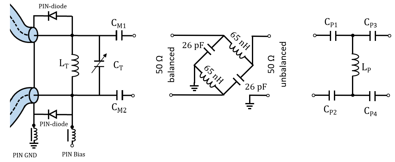
To miniaturize the large tuning inductor introduced in1 and allow for precise and easier tuning, a tunable capacitor CT was placed in parallel to inductors of different (smaller) values (Fig. 1a) ranging from LT = 27 nH (corresponding CT=53.5 pF) to LT=360 nH (no CT). Qunloaded and Qloaded were measured with a double-loop probe on a phantom (25L container filled with deionized water, 1.6g NaCl/L, DC conductivity ≈0.2 S/m, 1mL/L Magnevist). To determine SNR, GRE MR images (TE=10 ms, TR=300 ms, α=60°, FoV=300x300 mm2) were acquired in a 3T MR scanner (Siemens Magnetom Prisma Fit). In a first measurement series varying LT and CT, the matching capacitors CM1 and CM2 were not symmetric, showing that SNR suffered considerably depending on the difference of the two. Another measurement series with equal CM was therefore conducted. To further save space and reduce coupling between inductors, self-wound toroid inductors were built and miniature size preamplifiers with a size of 10.9x9.1x2.9 mm³ (MSM-123281, Microwave Technology, CA, U.S.A.) were used.
Fuse:
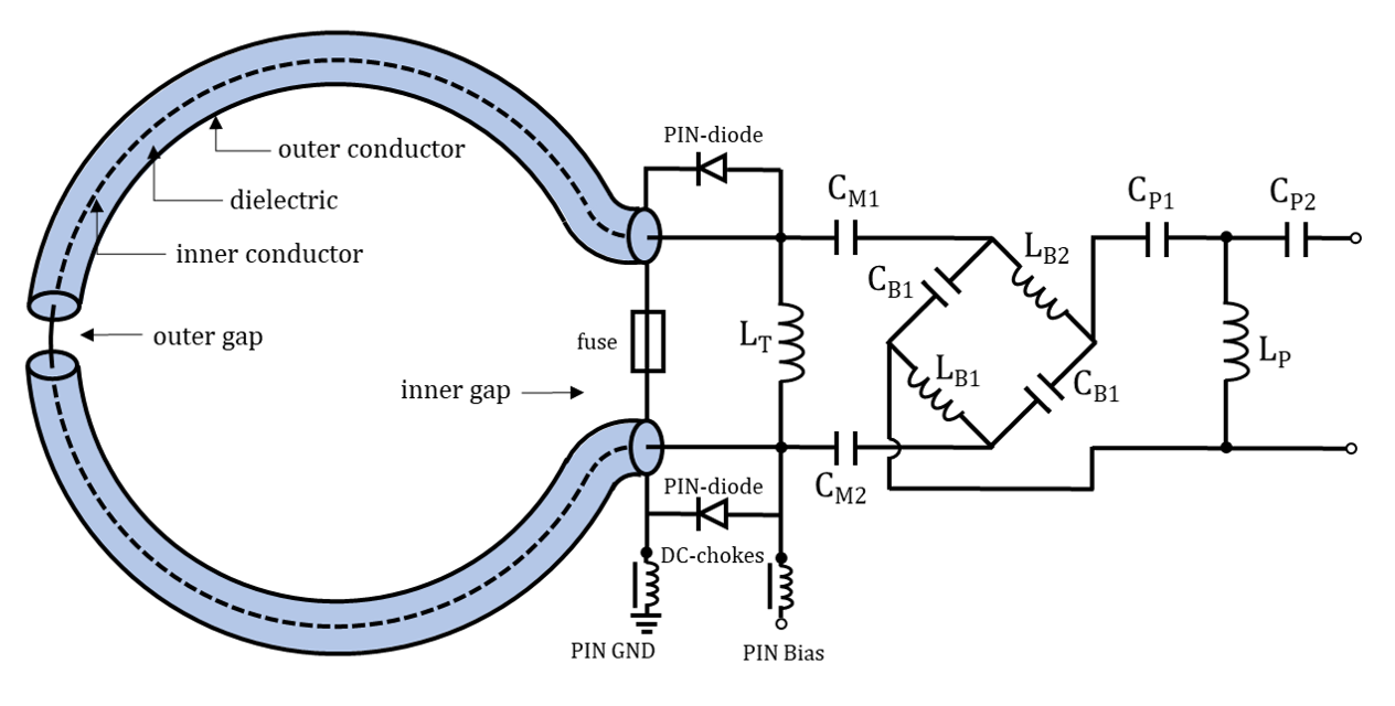
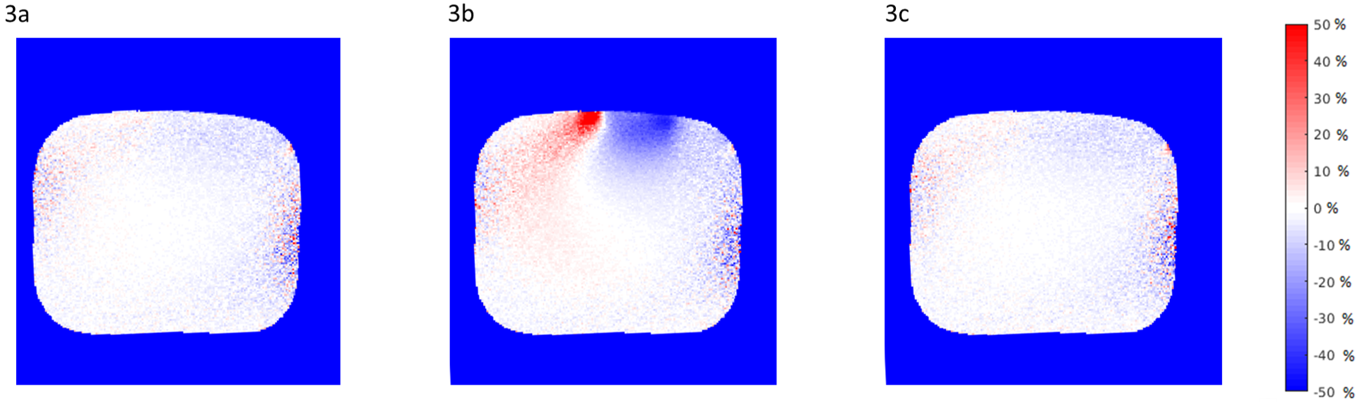
A fuse to spoil the resonance in case of too high current flow was placed in the middle of the outer conductor, since it is located at the position of the port and can therefore be included in an interface PCB within the same housing. To quantify the efficiency of the fuse, flip-angle maps employing the satTFL method6 (TE=1.9 ms, TR=6460 ms, α=80°, FoV= 399x399 mm2) were acquired with the body coil without and with the coaxial coil present. With the coaxial coil present, three configurations were studied: 1. with a normal working active detuning circuit, 2. with the active detuning circuit intentionally defective, and 3. with a blown fuse. The fuse was blown by running a sequence with high transmit power and the defective active detuning circuit.
Preamplifier decoupling:
A transformation of the preamp’s low input impedance to a short at the coil port suppresses current flow along the coil to minimize crosstalk in arrays. The necessary phase shift (>180°) was realized by combining a balun (Fig. 1b) and a lumped element high pass tee phase shifter (Fig. 1c) to avoid a long cable between the interface and the preamp. The balun shifts the phase by 180° and converts the balanced signal to an unbalanced signal, reducing common mode currents. After the balun, an unbalanced high pass tee is sufficient. The electrical circuit of the entire interface connected to the coaxial coil is shown in Fig. 2. Bench measurements and SNR scans as described above were performed to investigate the performance of the balun.
Results
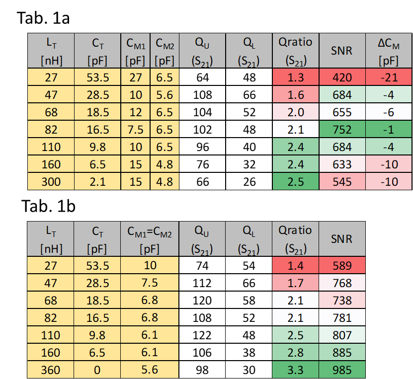
The performance of the interfaces with varying LT (and corresponding CT) are summarized in Tab. 1. In the measurements with ΔCM>0 (Tab. 1a) the Q-ratio (QU/QL) increases with increasing LT, whereas SNR is related to ΔCM. For the ΔCM=0 (Tab. 1b), both Q-ratio and SNR are increasing with increasing LT. The optimal single channel interface was found with LT=360 nH, no CT, and CM1=CM2=5.6 pF. The flip-angle ratio maps in Fig. 3 show (a) good decoupling from the body coil for the intact interface, (b) strong B1 artifacts (up to ±50% change) in case of the intentionally malfunctioning active detuning and (c) again good decoupling after the fuse was intentionally blown. Connecting the balun to the single-channel interface increased both QU an QL by more than 20% percent, also SNR increased by 11%.Conclusion
An optimized interface for a coaxial coil operated near its self-resonance was demonstrated: The importance of symmetric matching and the advantage of using a balun was shown, a fuse positioned at center of the outer conductor is efficient. Small toroidal inductors and a miniature preamplifier are proposed to save space and weight and thereby maintain flexibility when used in an array.Acknowledgements
This project was funded by the Austrian/French FWF/ANR grant, No. I-3618, “BRACOIL“.References
1 B. Zhang, D. K. Sodickson, and M. A. Cloos, “A high-impedance detector-array glove for magnetic resonance imaging of the hand", Nat. Biomed. Eng. 2: 570–577 (2018).
2 T. Ruytenberg, A. Webb, I. Zivkovic, “Shielded‐coaxial‐cable coils as receive and transceive array elements for 7T human MRI”, Mag. Reson. Med. (2019), eprint, https://doi.org/10.1002/mrm.27964
3 E. Laistler, E. Moser, “Handy magnetic resonance coils”, Nat. Biomed. Eng. 2: 557–558 (2018).
4 L. Nohava, et al., “Flexible multi-turn multi-gap coaxial RF coils (MTMG-CCs): design concept and bench validation”, Proc. Intl. Soc. Mag. Reson. Med. 27. 565 (2019).
5 R. Czerny, et al., “Flexible multi-turn multi-gap coaxial RF coils: enabling a large range of coil sizes”, Proc. Intl. Soc. Mag. Reson. Med. 27. 1550 (2019).
6 S. Chung, et al., “Rapid B1+ mapping using a preconditioning RF pulse with TurboFLASH readout”, Magn. Reson. Med. 64: 439–446 (2010).
Figures