4041
Comparison of magnetic and electric coupling coefficients for coaxial coils and standard loop coils1Division MR Physics - Center for Medical Physics and Biomedical Engineering, Medical University Vienna, Vienna, Austria, 2Massachusetts General Hospital, Harvard Medical School, A. A. Martinos Center for Biomedical Imaging, Charlestown, MA, United States
Synopsis
Coaxial coils as highly flexible elements of RF coil arrays have been proposed, and superior inter-element decoupling over standard loops has been reported, but so far without convincing explanation of the underlying mechanism. In an attempt for an explanation measurements of the magnetic and electric coupling coefficients for coaxial and standard loop coils were performed, and showed differences in the S21 findings and the coupling parameters, which are topic of further investigations.
Introduction
MRI phased arrays suffer from inter-element coupling, restricting coil design to fixed array layouts and limit the patient variability to be investigated. Coaxial coil elements [1] [2] offer higher flexibility and, therefore, increased filling factor compared to conventional coils, directly affecting SNR. Coaxial coil elements have been reported to show less interaction between adjacent elements [1] [2]. The mechanism why coaxial coils would (if at all) exhibit inherently lower inter-element coupling has not yet been explained satisfactorily. Reduced electric coupling due to a shielding effect of the outer shield of the coaxial cable [2] and more efficient preamp decoupling for coaxial coils [1] were suggested. To add to the discussion and investigate whether coaxial coils exhibit a different behavior w.r.t. magnetic and electric coupling leading to a similar effect to that presented for “self-decoupled” coils [3] we present measurements of the magnetic and electric coupling coefficients for coaxial and standard loop pairs.Methods
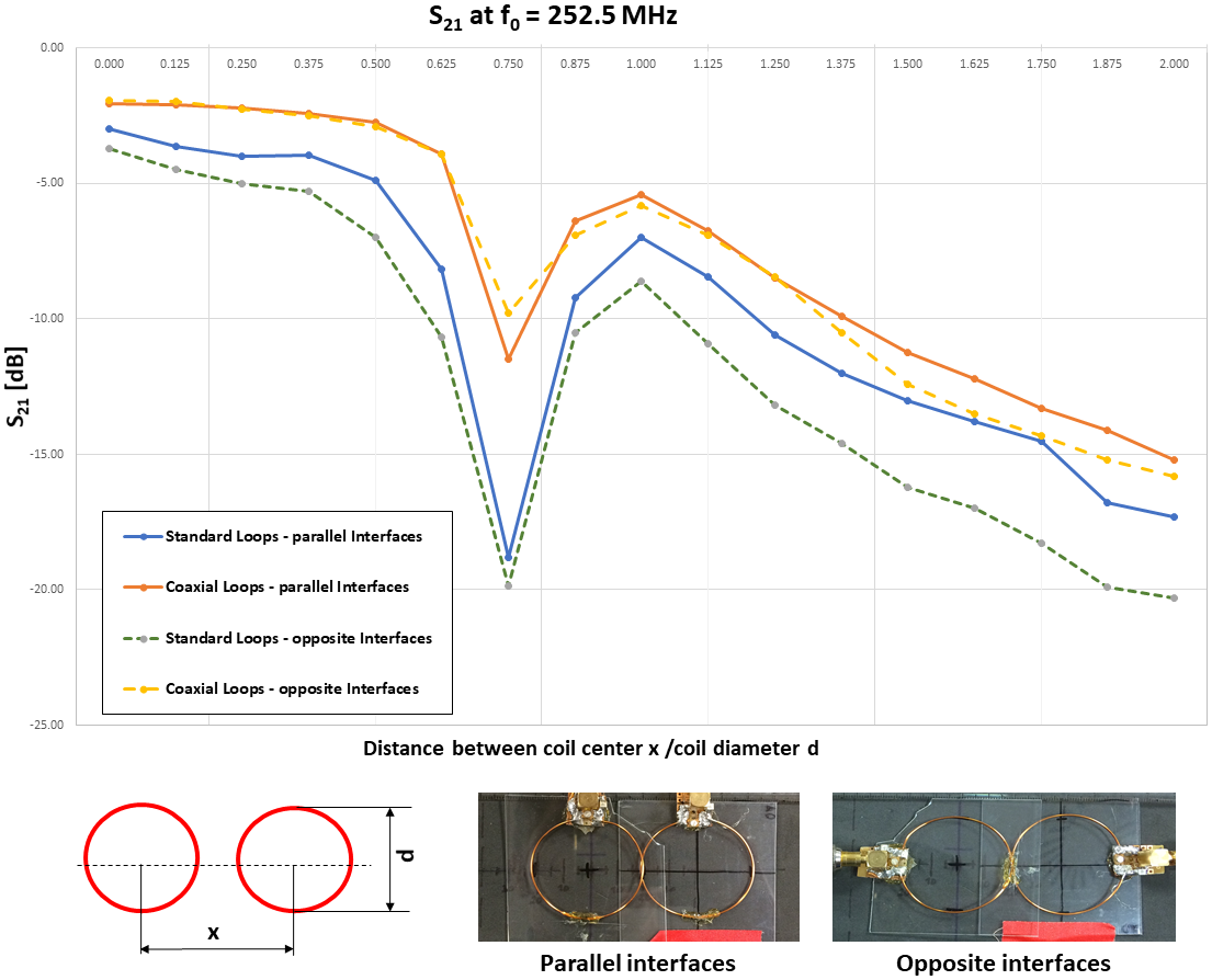
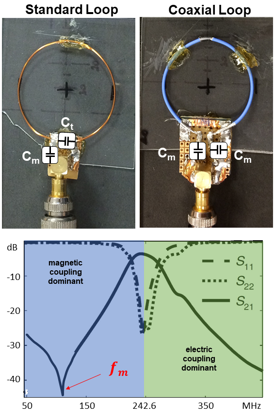
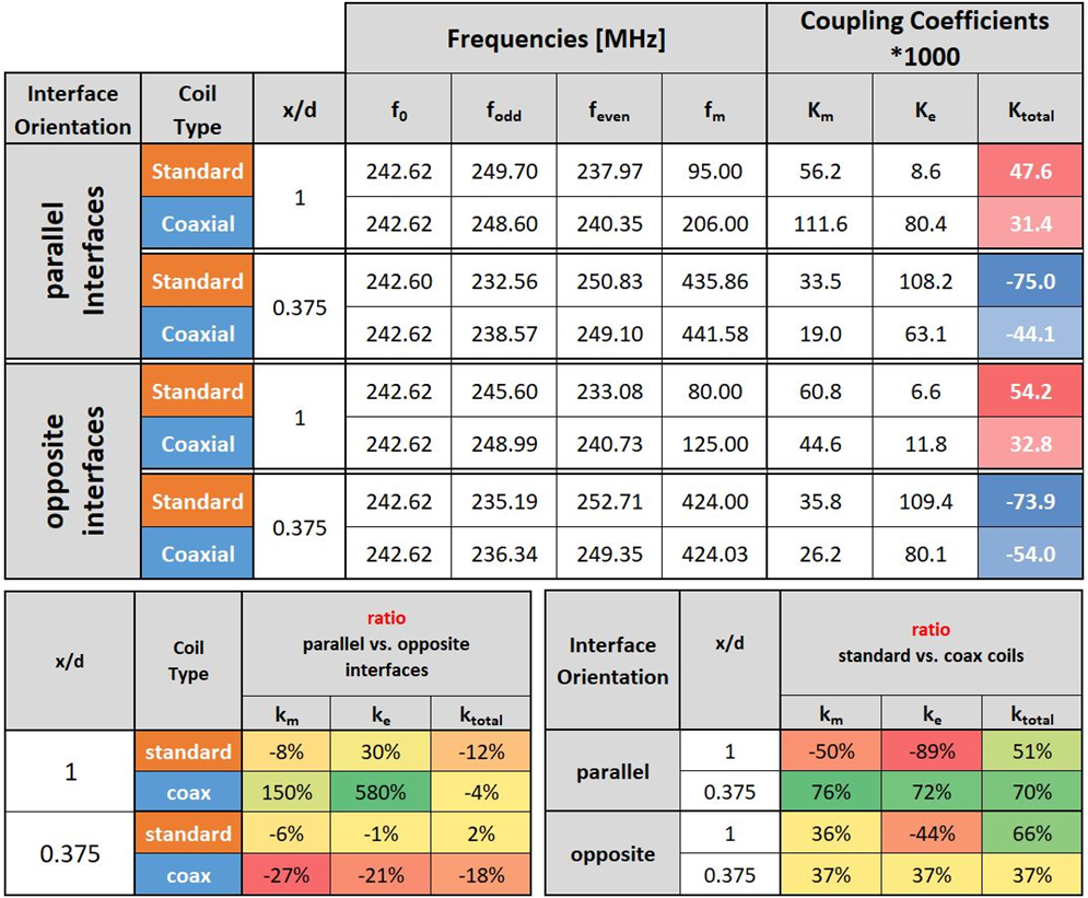
Magnetic and electric coupling coexist between adjacent resonators and a transmission zero at frequency fM is measured where the two contributions cancel. The dominant type of coupling can be derived from the position of fM relative to the resonance frequency f0 (fM < f0: magnetic coupling dominant, fM > f0: electric coupling dominant). By using the two-mode-frequency method, the resonant-mode-splitting frequencies fodd and feven can be observed, as soon as the two loops are over-coupled [4] [5]. The total coupling coefficient $$k_{total} = (k_m - k_e) / (1-k_m k_e)$$, magnetic coupling $$k_m = 1/2 * (((f^2_{odd} - f^2_0) / (f^2_{odd} - f^2_m)) + ((f^2_{even} - f^2_0) / (f^2_m - f^2_{even})))$$ and electric coupling $$k_e = (f^2_m / 2f^2_0) * (((f^2_0 - f^2_{odd}) / (f^2_m - f^2_{odd})) + ((f^2_0 - f^2_{even}) / (f^2_{even} - f^2_m)))$$ , can be derived from fodd, feven, fM, and f0 (see Fig. 3) [5].Two coaxial and two standard loops with diameters of 40 mm and a resonance frequency of 242.6 MHz (self-resonance of the coaxial elements (U = 2πr = 125 mm); see Fig. 2) and matched to 50 ohm. The coaxial loops used a 3.4 pF ceramic SMD capacitor Cm. The standard loops were tuned using a 1.4-3.0 pF tuneable capacitor Ct and matched using a 1.7 pF capacitor Cm. The four loops were used to observe coupling (ktotal, kE, kM) between them. Qloaded and Qunloaded values were acquired using a decoupled (-75 dB) double loop probe at 2 cm distance to the loop elements. A 4 mm polyurethane foam piece was placed between the loops and a loading phantom (5 liter H20 + NaCl, 1 mL/L Gd, DC conductivity = 0.2 S/m). Measurements were performed on a VNA (E5071C, Keysight Technology) with the coil interfaces on opposite sides of the coil elements, or parallel to each other (Fig. 1).
Results
The S21 decoupling of the standard loops is in general slightly better compared to the coaxial loops (see Fig. 1). The optimal overlap is achieved at the same relative position for both coil types. The Q-ratio = Qunloaded / Qloaded was 58 / 23 = 2.5 for coaxial elements and 109 / 27 = 4.0 for standard loops.The orientation of the interfaces for the coaxial loops changes km and ke by 37 to 76% whereas only little change is found for the standard loops. For the total coupling coefficient ktotal, this pronounced difference is not observed. Standard coils show an overall higher ktotal of 37 to 70% in all investigated configurations (See Fig. 3).
Discussion and Conclusion
The findings for the coupling coefficients would indicate lower coupling for coaxial coils, however, the measurement of S21 shows the exact opposite. The reason for this contradictory result is still unclear and will be further investigated. The higher Q-ratio for standard loops could be explained by increased coil noise for the coaxial elements. Given that these measurements have only been performed at one coil size and frequency, and at the self-resonance of the coaxial coils, in addition to the contradictory results for k and S21, more in-depth experiments are required.Acknowledgements
This work was supported by OENB grant #17980.References
[1] B. Zhang, D. K. Sodickson and M. A. Cloos, "A high-impedance detector-array glove for magnetic resonance imaging of the hand," Nature Biomed. Eng., 2018.
[2] T. Ruytenberg, A. Webb and I. Zivkovic, "Shielded-coaxial-cable coils as receive and transceive array elements for 7T human MRI," Magn. Reson. Med., pp. 1-12, 2019.
[3] X. Yan, J. C. Gore and W. A. Grissom, "Self-decoupled radiofrequency coils for magnetic resonance imaging," Nat. Commun., no. 9, p. 3481, 2018.
[4] J. S. Hong and M. J. Lancaster, "Couplings of Microstrip square open-loop resonators for cross-couple planar microwave filters," IEEE Transactions on Microwave theory and techniques, no. 44(12), pp. 2099-2109, 1996.
[5] Q. X. Chu and H. Wang, "A compact open-loop filter with mixed electric and magnetic coupling," IEEE Transactions on Microwave theory and techniques, no. 56(2), pp. 431-439, 2008.
Figures