4037
32-Channel Lightweight Dipole RF Array for Cardiac MRI at 7.0 Tesla1Berlin Ultrahigh Field Facility, Max-Delbrück-Center for Molecular Medicine in the Helmholtz Association, Berlin, Germany, 2MRI.TOOLS GmbH, Berlin, Germany, 3Experimental and Clinical Research Center (ECRC), a joint cooperation between the Charité Medical Faculty and the Max-Delbrück Center for Molecular Medicine, Berlin, Germany
Synopsis
A lightweight, high-density transceiver RF array of 32 compact self-grounded bow-tie antennas was developed, manufactured, evaluated, and applied for cardiac MRI at 7.0 T. Our work contributes to the technological basis for future clinical assessment of parallel transmit techniques of the heart for optimization of RF antenna placement and RF antenna count with the goal to approach ultimate SNR in ultrahigh field MRI of the heart.
Introduction
An increasing number of reports eloquently speaks about cardiovascular MRI at 7.0 T, including first clinical applications. An MRI of the upper torso and the heart at 7.0 T is susceptible to non-uniformities in the RF transmission field (B1+) due to the short RF wavelength. To offset constructive and destructive interferences, pioneering RF antenna arrays have employed electric dipoles. To enable efficient RF power transmission, the antenna size can be as long as 300 mm for a half-wavelength dipole at 7.0 T.1 This geometric constraint imposes a severe constraint for the design of high-density, transceiver arrays confined to cardiac fields of view. To address the limitation this work demonstrates the feasibility of a high density, 32-channel array comprised of small size, compact self-grounded bow-tie (SGBT) building bocks for cardiac MRI at 7.0 T.Methods
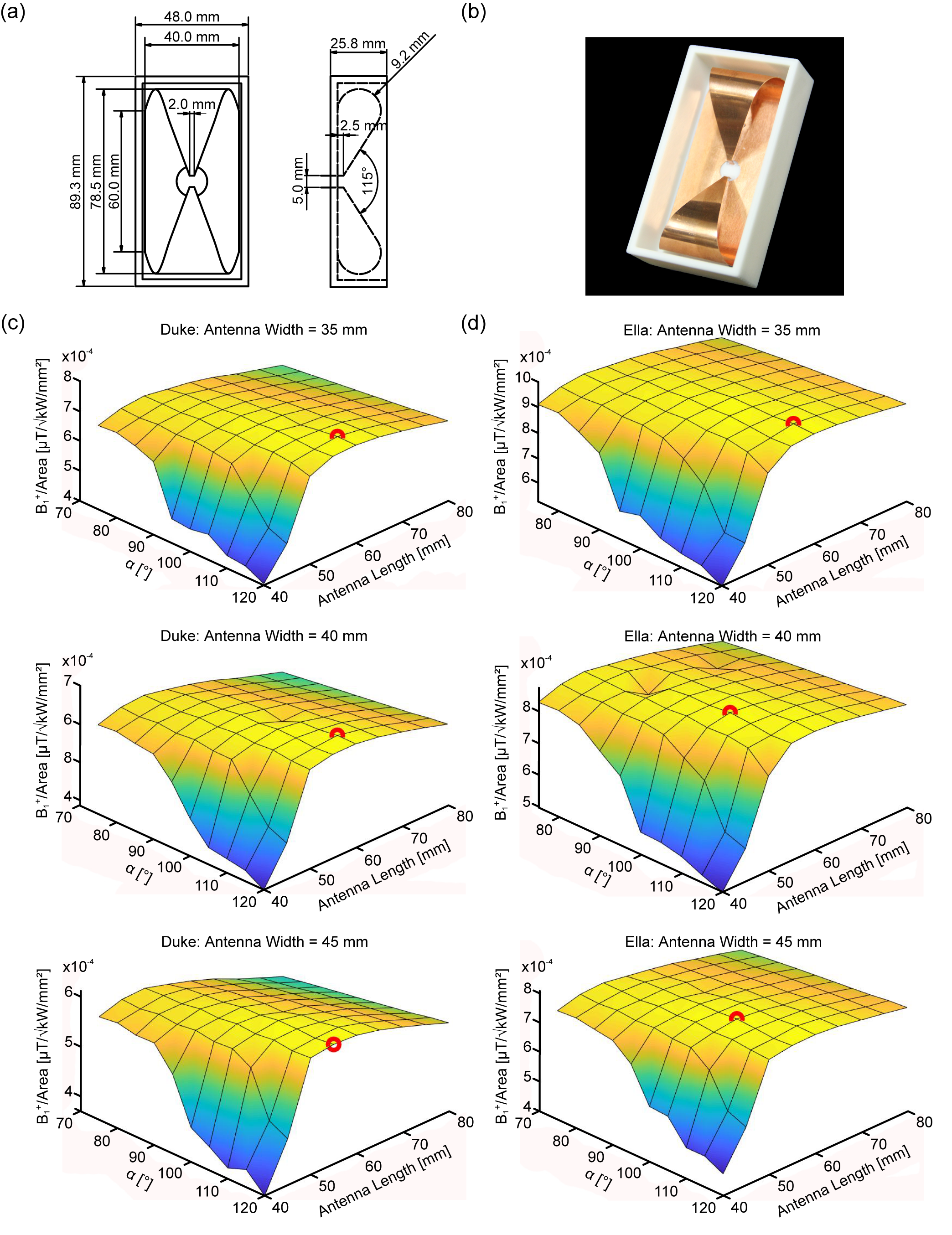
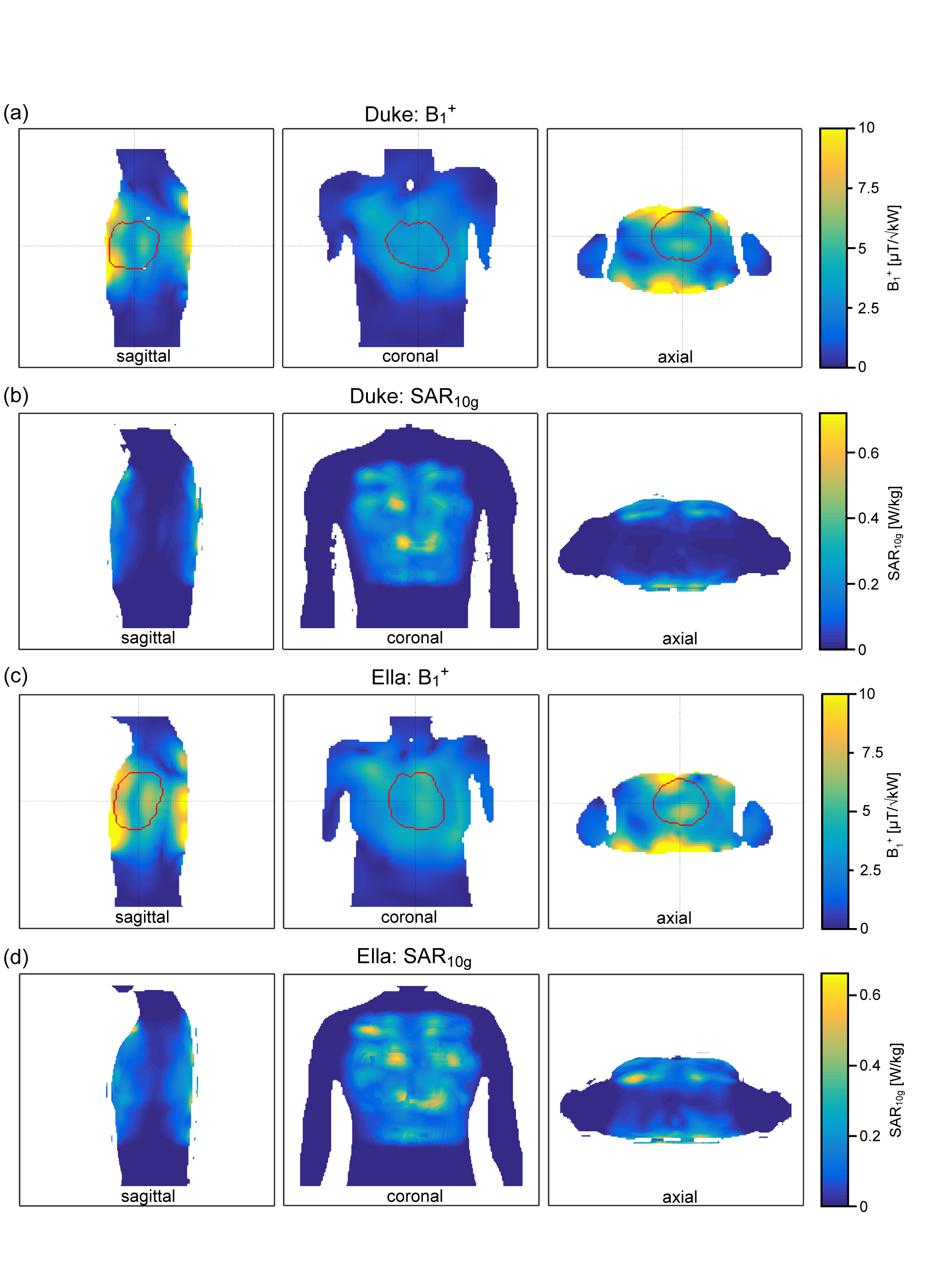
The RF building block comprises an SGBT antenna immersed in 99.9% D2O (Sigma Aldrich GmbH, Munich, Germany) for RF wavelength shortening. The antenna and building block design parameters (length, angle, and width) were investigated with CST Microwave Studio (CST Studio Suite 2019, Dassault Systèmes, Vélizy-Villacoublay Cedex, France) to maximize B1+ in relation to the building block footprint for the cardiac field of view. Low loss Xanthan/LGB/Agarose hydrogel2 was employed to ensure low reflection wave propagation of the building block to the subject. Electromagnetic field (EMF) simulations of the 32-channel antenna array were performed on a phantom (ε = 78.4, σ = 0.64 S/m) and the torso of the human voxel model Duke and Ella.3 Results of the human voxel models were used for a phase shimming approach with the target function maximizing the min B1+ value in the heart as target region. SAR calculations at 297.2 MHz were normalized to 1 W input power and averaged over 10 g according to IEEE/IEC standard 62704-1.4 Proof-of-principle phantom experiments and in vivo studies were conducted with a 7.0 T whole-body MRI system (MAGNETOM, Siemens Healthineers, Erlangen, Germany).5Results
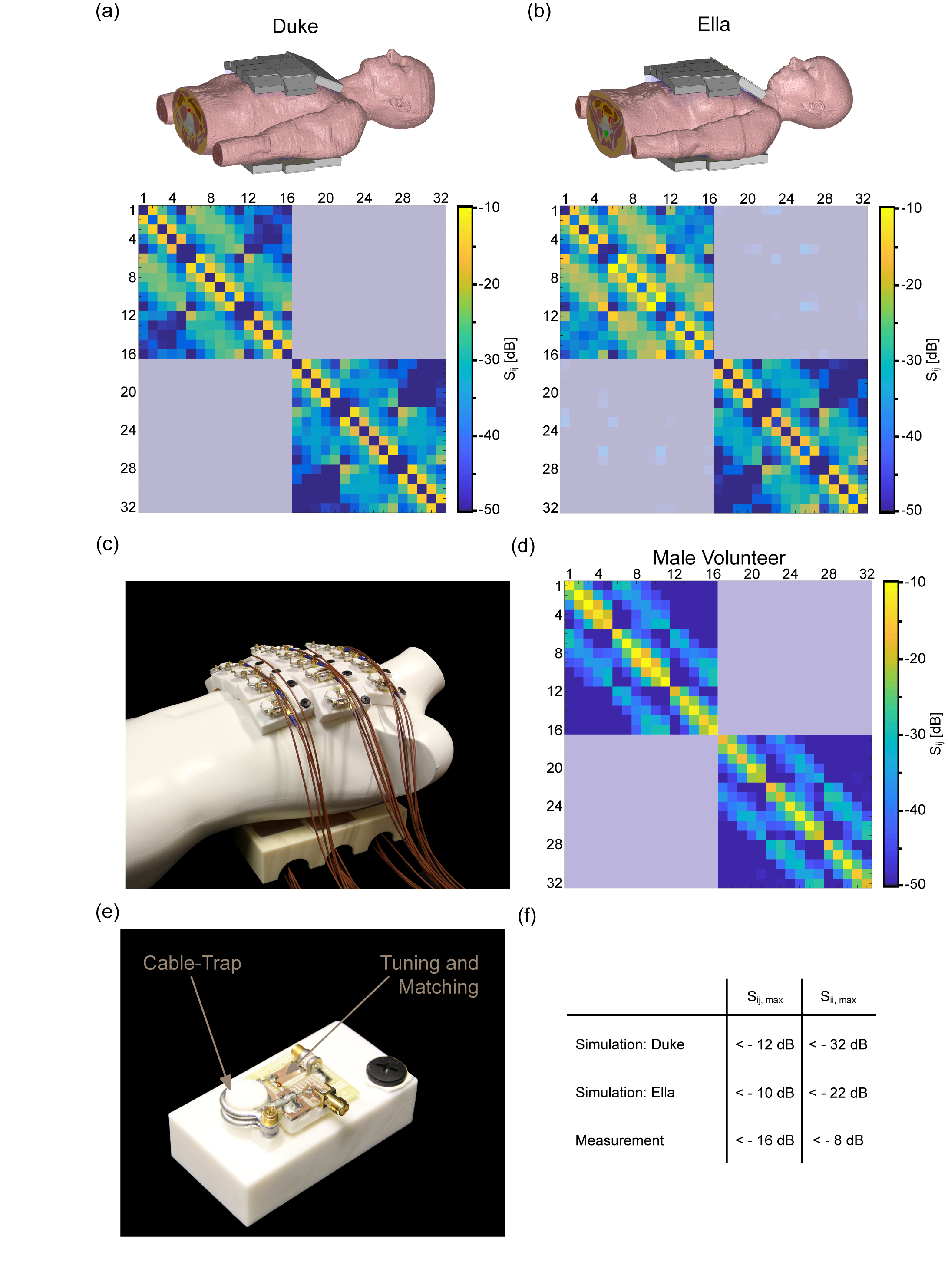
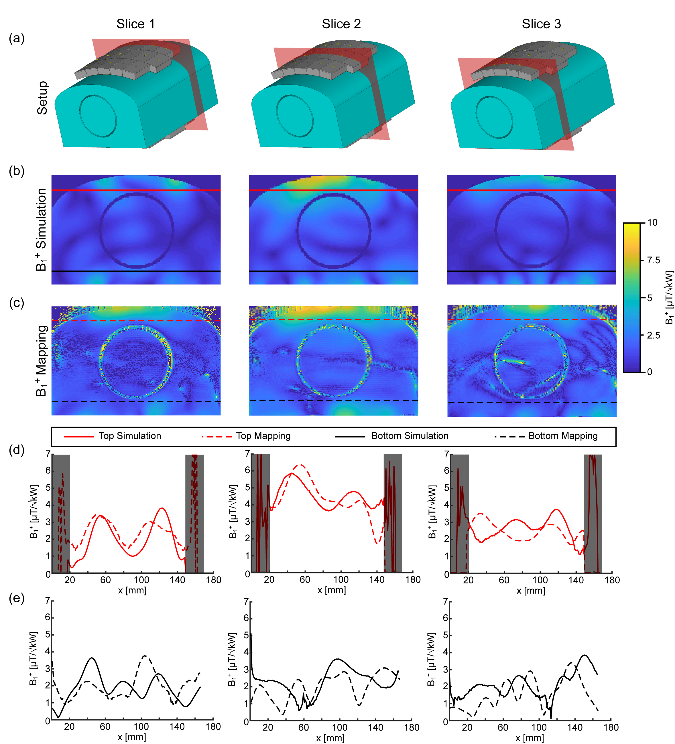
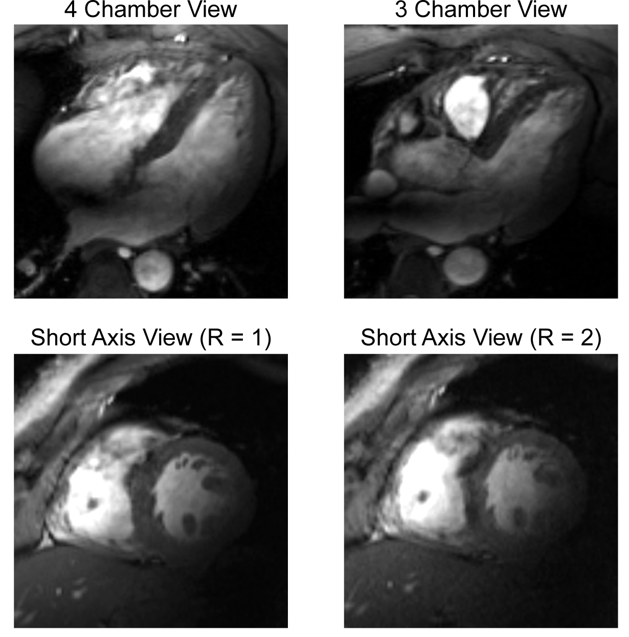
Figure 1 demonstrates the B1+ field per building block footprint for a target area comprising the heart of the human voxel models Duke and Ella at antenna widths of 35 mm, 40 mm, and 45 mm. All simulations showed a lower B1+ for Duke compared to Ella so that design optimization was primarily focussed on the male voxel model. For an antenna width of 40 mm (length = 60 mm, α = 115°) a worst-case coupling of -10 dB was obtained for simulations. For measurements worst case coupling of and -16 dB was found. The final SGBT building block exhibits a weight of 156 g and provides a small size of (48.0x89.3x25.8) mm³ (Figure 1 a-b), which permits a lightweight, high-density array tailored for the cardiac imaging. The scattering matrix obtained for a 32-channel array for Duke, Ella, and a healthy male volunteer is shown in Figure 2. The reflection was found to be < -22 dB with a coupling of < -10 dB for simulations. For a healthy subject a reflection of -8 dB and a coupling of -16 dB were observed. B1+-shimming yielded a phase setting that affords a mean value of 4.59 μT/√kW (min = 2.49 μT/√kW) for Duke’s and 5.01 μT/√kW (min = 2.33 μT/√kW) for Ella’s heart (Figure 3). In the torso phantom B1+ scaled simulations, and B1+ measurements in Figure 4 (a-c) agree qualitatively. Figure 4 (d-e) shows B1+ field plots along indicated lines in Figure 4 (b-c). The mean losses in the signal chain were measured to be below -3.35 dB for all channels, including the RF power splitter, the transmit/receive switch, and cable losses. Peak SAR10g derived from the EMF simulations showed < 0.72 W/kg for Duke and Ella, which limits the forward power to 30 W for the normal operating mode governed by the IEC guidelines. For in vivo proof of principle short axis, 3 and 4 chamber views of the heart of a healthy male subject are shown in Figure 5 at a spatial resolution of (1.4x1.4x4.0) mm².Discussion and Conclusion
The proposed SGBT building block pushes the boundaries for high-density dipole RF array configurations tailored for cardiac MRI at 7.0 T. The building block footprint is reduced by 64% versus commonly used fractionated dipole1, 59% versus Bow-Tie building block6 and 43% versus Single-Side Adapted Dipole configurations7. The presented 32-channel RF array exhibits the highest density of Tx/Rx elements reported for cardiac imaging at 7.0 T. The channel density is increased by the factor of 2 over a bow-tie cardiac array8 and fractionated loop-dipole configurations9. The in vivo proof-of-principle study using a low loss hydrogel shows a small signal void in the heart due to placement accuracy of the anterior antenna array. Taking advantage of the proposed modular design we anticipate furthering research into optimizing antenna placement to enhance B1+ excitation efficiency, uniformity, and coverage of the human heart with the goal of approaching ultimate signal to noise ratio (SNR) for cardiac MRI at 7.0 T along with facilitating larger acceleration factors for parallel imaging.Acknowledgements
This project has received funding from the European Research Council (ERC) under the European Union's Horizon 2020 research and innovation program under grant agreement No 743077 (ThermalMR).References
1. Raaijmakers AJE, Italiaander M, Voogt IJ, et al. The fractionated dipole antenna: A new antenna for body imaging at 7 Tesla. Magn Reson Med. 2016;75(3):1366-1374. doi:10.1002/mrm.25596
2. Trefná HD, Ström A. Hydrogels as a water bolus during hyperthermia treatment. Phys Med Biol. 2019;64(11). doi:10.1088/1361-6560/ab0c29
3. Christ A, Kainz W, Hahn EG, et al. The Virtual Family - Development of surface-based anatomical models of two adults and two children for dosimetric simulations. Phys Med Biol. 2010;55(2). doi:10.1088/0031-9155/55/2/N01
4. IEEE 62704-2-2017 - IEEE/IEC International Standard -- Determining the peak spatial-average specific absorption rate (SAR) in the human body from wireless communications devices, 30 MHz to 6 GHz -- Part 1: General Requirements for using the Finite Differe. 2017.
5. Yarnykh VL. Actual flip-angle imaging in the pulsed steady state: A method for rapid three-dimensional mapping of the transmitted radiofrequency field. Magn Reson Med. 2007;57(1):192-200. doi:10.1002/mrm.21120
6. Winter L, Özerdem C, Hoffmann W, et al. Design and Evaluation of a Hybrid Radiofrequency Applicator for Magnetic Resonance Imaging and RF Induced Hyperthermia: Electromagnetic Field Simulations up to 14.0 Tesla and Proof-of-Concept at 7.0 Tesla. Yacoub E, ed. PLoS One. 2013;8(4):e61661. doi:10.1371/journal.pone.0061661
7. Raaijmakers AJE, Ipek O, Klomp DWJ, et al. Design of a radiative surface coil array element at 7 T: The single-side adapted dipole antenna. Magn Reson Med. 2011;66(5):1488-1497. doi:10.1002/mrm.22886
8. Oezerdem C, Winter L, Graessl A, et al. 16-channel bow tie antenna transceiver array for cardiac MR at 7.0 tesla. Magn Reson Med. 2016;75(6):2553-2565. doi:10.1002/mrm.25840
9. Ertürk MA, Raaijmakers AJE, Adriany G, Uğurbil K, Metzger GJ. A 16-channel combined loop-dipole transceiver array for 7 Tesla body MRI. Magn Reson Med. 2017;77(2):884-894. doi:10.1002/mrm.26153
Figures