4034
A tight-fit 8-channel transceiver array for simultaneous EEG-fMRI at 7-Tesla1University of Glasgow, Glasgow, United Kingdom
Synopsis
Simultaneous EEG-fMRI exploits complementary information from the two modalities and offer insights into the dynamics of the brain function. In this work, we developed a tight-fit 8-channel transceiver head coil which facilitates the use of a 64-electrode EEG setup for simultaneous EEG-fMRI at 7T. Influence of the EEG cap on transmit and receive performance of the coil is presented in this work.
Introduction
Simultaneous EEG-fMRI exploits complementary information from the two modalities and offer insights into the dynamics of the brain function [1-3]. The increased spatial resolution available at ultra-high field (UHF, ≥7T) makes simultaneous EEG-fMRI an attractive combination at 7T. The EEG setup requires space and provision to route the cables to the amplifier pack placed behind the coil, which is currently not possible with the most commonly used 7T head coil (Nova Medical Inc). We have developed a tight-fit 8-channel transceiver head coil [4] for simultaneous EEG-fMRI at 7T. In this abstract we present initial phantom results characterising the influence of the EEG cap on the RF coil performance.Methods
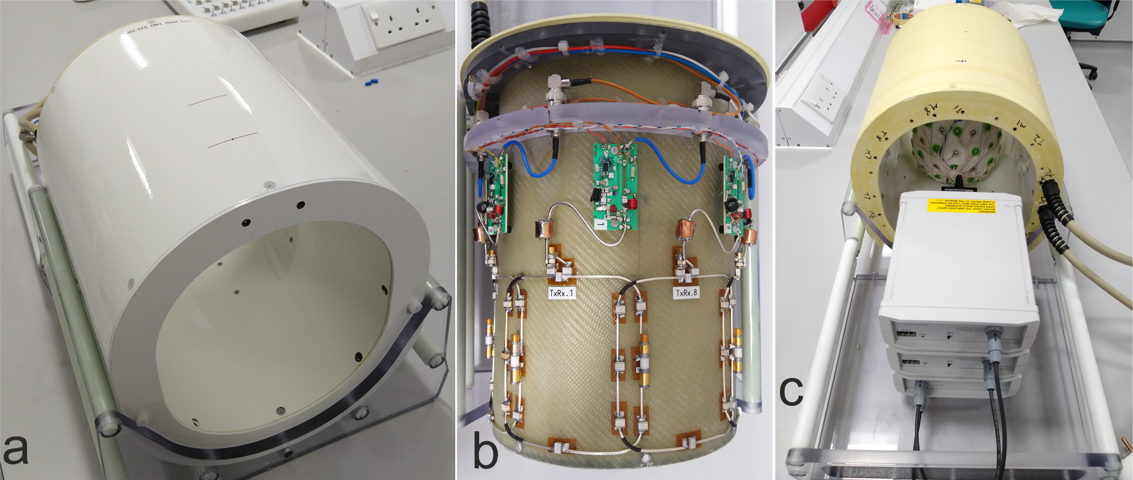
The 8-channel transceiver array is constructed on a fiberglass 21cm x 24cm tube with 3mm wall thickness. The coil is locally shielded and the distance to the shield is 30mm. To prevent eddy currents, a slotted pattern was etched on a double layered flex PCB with polyimide substrate and 7µm thick copper. Adjacent coil elements are geometrically overlapped, and the coil elements measure 12cm along the z-direction. Custom-built TR switches with preamps are part of the coil housing. A picture of the coil setup and the internal electronics is shown in Fig.1. A view of the EEG-fMRI setup from the service end is shown in Fig.1c.All MR measurements were conducted on a Siemens 7T Terra system. We use a home-built 1x8 splitter with 45° phase offsets to drive the coil in the circularly polarised (CP) mode. The EEG setup (Brain Products GmbH, Germany) consisted of a 64-electrode BrainCap and a battery pack with two 32-channel BrainAmp amplifiers – all stacked behind the coil housing on the coil holder (Fig.1c).
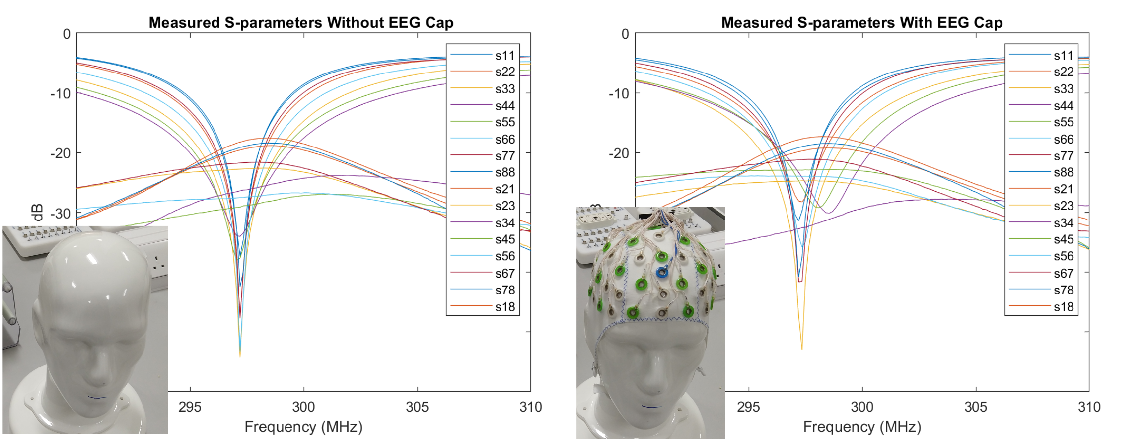
Each coil element consisted of seven fixed capacitors (6.8pF, 800C series, AT Ceramics, USA) and one variable capacitor (5610, Johanson, USA). The coil elements are tuned and matched to a head and shoulder phantom filled with tissue equivalent solution (εr= 43 and σ = 0.39). To characterise the influence of the 64-electrode EEG cap, we measured S-parameters, SNR maps and B1+ maps with and without the EEG cap.
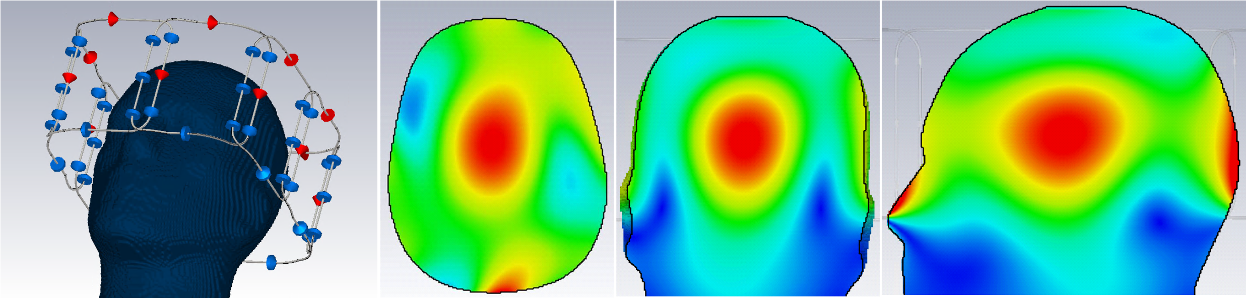
A numerical model of the coil was created in CST Studio Suite (Dassault Systèmes) and the tuning, matching and decoupling of the coil elements was optimised by loading the coil with the head and shoulder phantom. The coil model included component losses from the datasheet.
Results
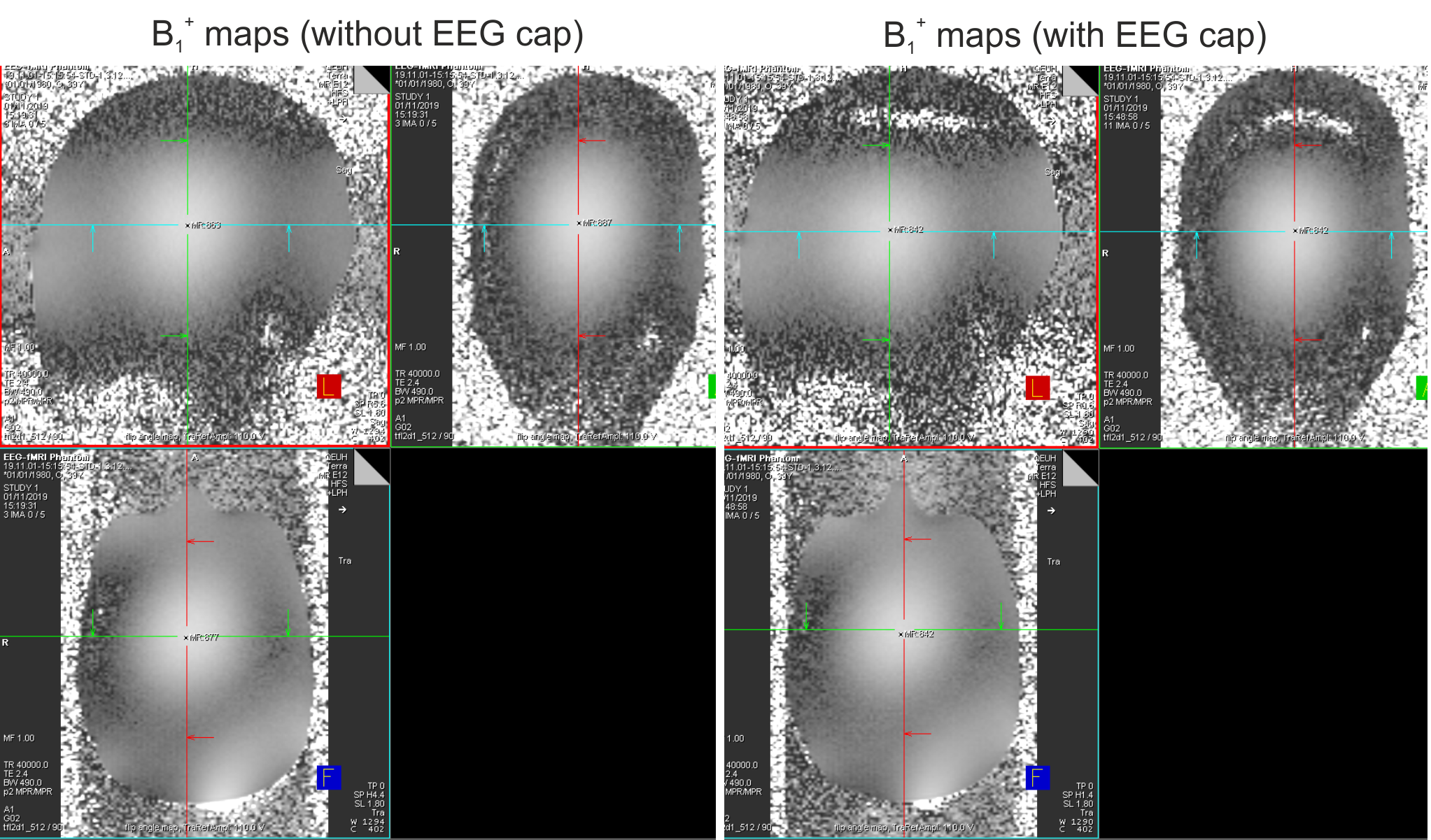
The coil elements were matched to better than -30dB and the average decoupling between adjacent elements was -20.02dB, with maximum coupling of -15.9dB. The same measurements were repeated after fixing the EEG cap on the phantom. The electrodes were also connected to the amplifiers powered by the battery pack. The coupling behaviour remained consistent with a maximum coupling of -15.5dB and average value of -19.8dB. Larger influence on the coil match was noticed as shown in the S-parameter plots in Fig.2.A screenshot of the coil model and the simulated field maps is shown in Fig.3. The peak B1+ in the simulated field map is 149nT/V. Measured B1+ maps acquired using the head and shoulder phantom is shown in Fig.4. The peak B1 in the center of the coil corresponds to 136nT/V, with the voltage referenced to the coil input. The change in the maximum flip angle in the center is about 5% and the spatial distribution of the B1+ field was not altered when the EEG cap was added. Furthermore, the magnitude and distribution of the measured maps matches well with the simulated results.
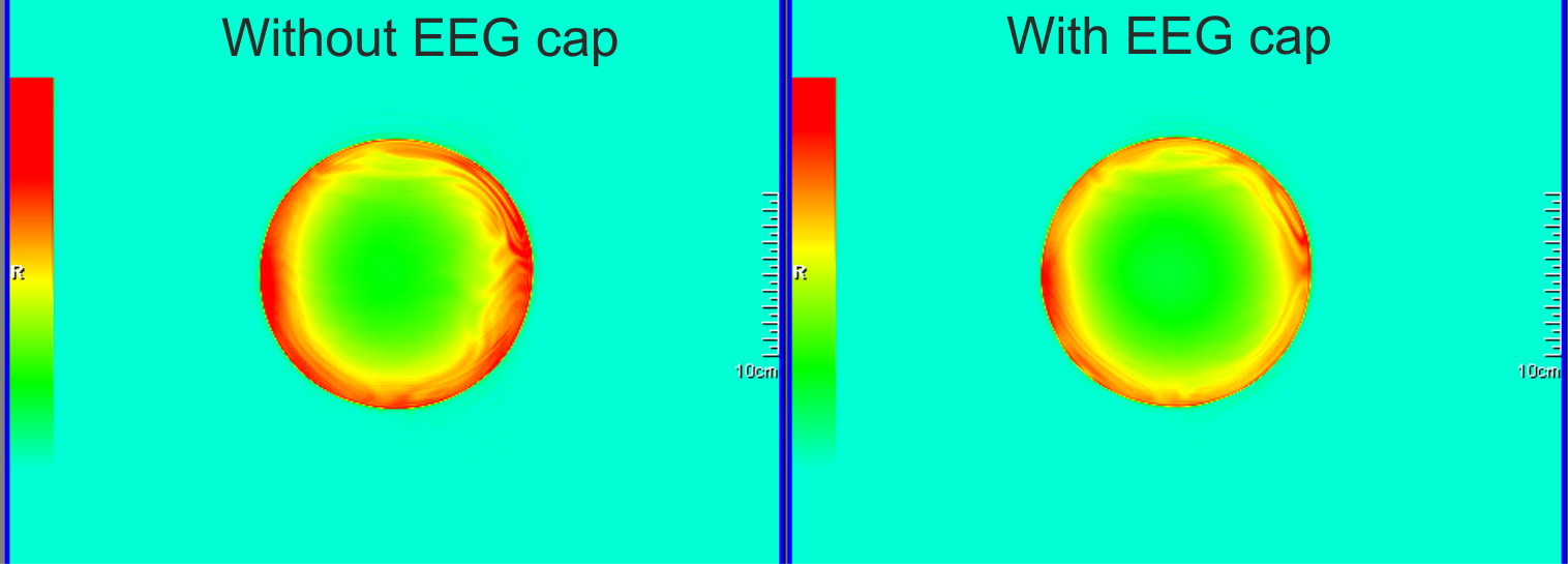
Signal to noise ratio (SNR) maps were acquired using the coil-utils tool in the scanner. A 175mm diameter spherical oil phantom was used for the SNR maps. The SNR in the central slice reduced by 14% from 152.4 to 134 when the EEG cap was added. However, no local variations are seen (Fig.5).
Discussion
We have evaluated the influence of a 64-electrode EEG cap on transmit and receive performance of a tight-fit 8-channel transceiver array. The open design concept of the coil housing allowed sufficient space for the EEG cap and the cable bundle could be easily attached to the amplifier and battery pack stacked in the coil holder. While loss in transmit efficiency and SNR was observed in the presence of the EEG cap, the maps presented in figures 4 and 5 demonstrate that the spatial distribution remains unaltered.Future work will include EM simulation with different human body models and assessment of the effect of EEG electrodes on B1+ and SAR distribution by comparing simulation results with and without the EEG cap. Furthermore, we will also measure the temperature increase due to RF induced heating on a suitable phantom and assess the impact of adding the EEG cap.
Acknowledgements
No acknowledgement found.References
1. Pisauro M, Fouragnan E, Retzler C et al. Neural correlates of evidence accumulation during value-based decisions revealed via simultaneous EEG-fMRI. Nat Commun 8, 15808 (2017)
2. Fouragnan, E., Retzler, C., Mullinger, K. et al. Two spatiotemporally distinct value systems shape reward-based learning in the human brain. Nat Commun 6, 8107 (2015)
3. Jorge J, Grouiller F, Ipek O et al. Simultaneous EEG–fMRI at ultra-high field: Artifact prevention and safety assessment. Neuroimage 105 (2015) 132-144.
4. Avdievich A, Giapitzakis I, Pfrommer A et al. Decoupling of a double‐row 16‐element tight‐fit transceiverphased array for human whole‐brain imaging at 9.4 T. NMR in Biomedicine. 2018:31:e3964
Figures