4032
Flexible torso array coil for Fast Field-Cycling MRI at 8.5 MHz1School of Medical Sciences, Aberdeen Biomedical Imaging Centre, University of Aberdeen, Aberdeen, United Kingdom, 2Magnetic Resonance Imaging, GE Healthcare, Waukesha, WI, United States
Synopsis
An array coil for 0.2 T reception has been developed for colon and heart studies in a FFC-MRI system. The array consists of 3 element posterior/anterior sections, with 16cm loops arranged in a “venn” pattern.
Minimizing conductor losses and noise figure over varying loading is particularly important in a low field system.
A two-turn litz arrangement was chosen offering good flexibility and Qu/Ql ratios. Interfacing electronics component topologies were simplified losses keping losses to a minimum. Matching, blocking, decoupling, and preamplification reside at element. Packaging is flexible textiles and substrates.
The resulting array conforms and retains performance with varying anatomy.
Introduction
Fast Field-Cycling MRI (FFC-MRI) is a new low-field method, which aims to exploit contrast arising from the variation of T1 with field strength (T1-dispersion) and allowing access to magnetic fields as low as 200 µT while retaining relatively high SNR. Studies are underway in our laboratory, measuring relaxation signatures of various healthy and diseased tissues [1]. Generally, signal acquisition is done at or near 0.2 T (8.5 MHz). To date, studies have been conducted with single-channel coils on the head, knee, and female breast, with each coil requiring careful tuning per volunteer to optimize performance. Clinical studies are commencing which involve relaxation dispersion characterizations of colon and heart tissues.A torso array receiver coil has been developed for those applications with the goal of an anatomy-conforming design that can be applied quickly, requiring no patient-to-patient adjustments to achieve high performance. This is particularly challenging at low field strengths where coil losses can limit the achieved SNR [2].
The coil consists of an anterior/posterior pair totaling 6 independent array elements in an effort to boost SNR relative to a single-channel coil [3].
Methods
Coil loop sizes were based on a commercial 1.5T array coil (GE Healthcare GEM anterior) with an approximate 16 cm diameter. Desired volume field-of-view (FOV) was ~30cm, which was achieved with 3 loops in a “Venn” configuration for both anterior and posterior coils (see Figure 3).Three types of conductor were investigated, namely (a) solid 0.22 mm copper wire; (b) litz wire, single-turn; (c) litz wire, 2 turns. The resulting coils, of similar geometry, were evaluated and compared for acceptable losses, flexibility, and ease of interfacing. The litz wire utilized was Elektrisola HF-Litz 1600 strand x 0.020 mm with bundle diameter of approximately 1.5 mm.
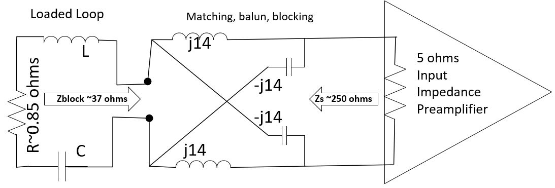
Because of the flexible, adaptable nature of the coil array, overlap decoupling needed to be augmented along with preamplifier decoupling [2]. Preamplifier decoupling was achieved by utilizing a high matching impedance transformation and an amplifier optimized for a >150 ohm source (Wantcom WMA-08HA) (Figure 2). The preamplifier, matching, and protection circuitry were integrated onto a circuit board dimensioned ca. 5 cm x 5 cm.
Results
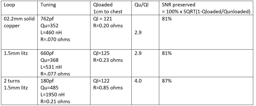
Test data (Figure 1) indicates the achieved performance for a 2.2 mm, single turn, solid copper wire loop; a single turn, 1.5 mm litz wire loop; and a two turn, 1.5 mm litz wire loop. Inductances are calculated from the needed capacitance to resonate the loop at 8.5Mhz. Resistances are calculated from the reactances and measured Qs. “SNR preserved” is derived from the loaded to unloaded Q ratios where:SNR Preserved (%) = 100 * SQRT(1 - Qloaded/Qunloaded)
The solid wire is rejected because of lack of mechanical flexibility and higher losses for a given diameter conductor versus the litz wire. The 2-turn litz implementation was selected because of the higher preserved SNR. Additionally, the loaded resistance of 0.85 ohm is likely to be easier to interface than the single-turn coil’s 0.23 ohm impedance.
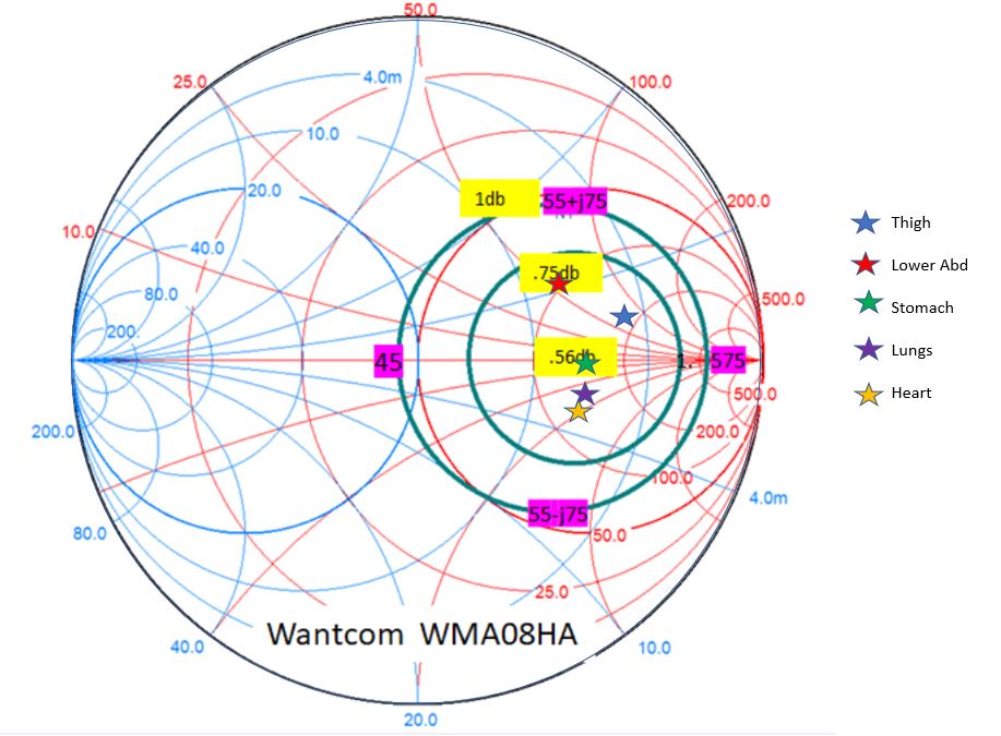
Under various loading conditions, the measured source impedances were found to stay inside the 1dB noise figure circle, indicating that the SNR will be degraded by less than 0.5db (approximately 5% ) upon loading the coil array (Figure 3).
The losses from components required to interface the loop were characterized and determined to add about .07 ohms, further reduce the SNR by 5%.
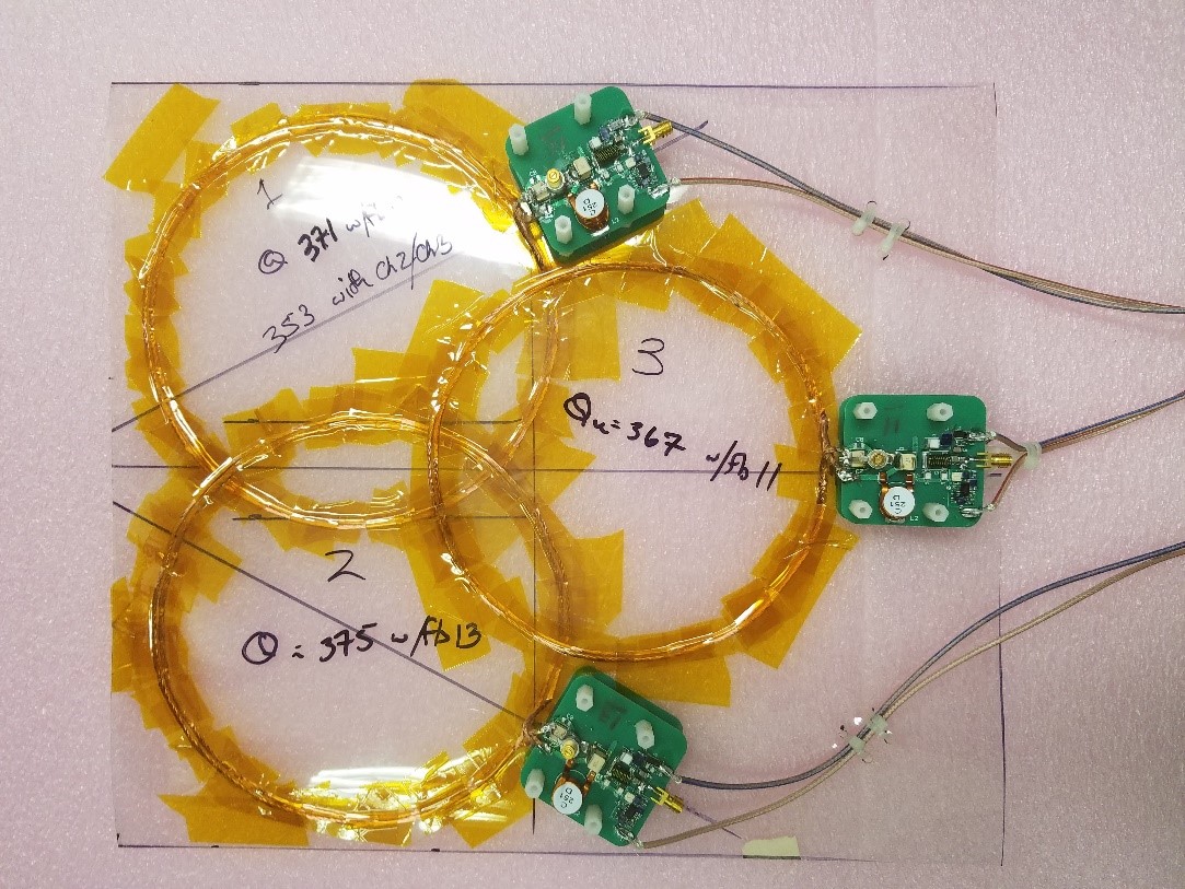
Figure 4 shows the 3 loop anterior coil, before packaging, interfaced to the preamplifiers. The interface board providing matching, balun functionality, transmit decoupling, preamplifier protection, as well as the low noise preamplifier function.
Discussion
Preserving available SNR at low fields is challenging because coil and component losses can be significant relative to body losses. A coil that couples well to the body, and minimizes other component losses/noise was our design goal.SNR degradation due to coil losses from a 2-turn litz loop is determined to be nominally 13%. Cutting those losses in half (doubling the unloaded Q), could improve this loss to 8%, but the reduction in coil flexibility and ease of application may be unsatisfactory for our applications.
Losses from the interfacing components reduce SNR by about 5%. It is possible that lower loss components or another interfacing scheme could ease some of this penalty.
The preamplifiers optimal noise figure lowers SNR by about 6%, and varying loading can add a few % of SNR loss. This additional loss could possibly be recovered with careful tuning of the coil elements on a volunteer to volunteer basis.
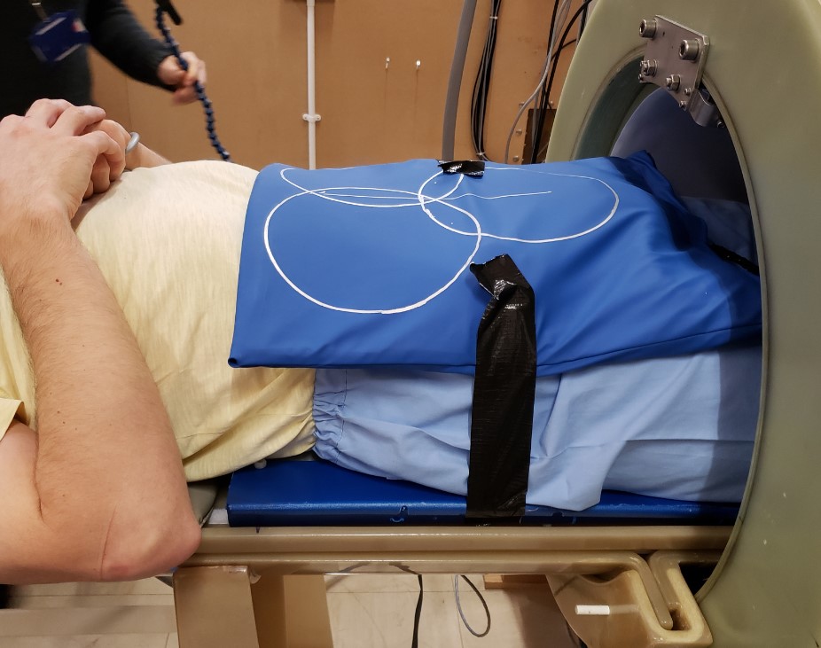
The coil array pair seems to be well-tolerated by volunteers during loading experiments, and conforms well across multiple torso regions (Fig. 5).
Array reconstructed phantom images indicate that the field-of-view and homogeneity are appropriate for human studies.
Conclusion
A coil array has been developed that achieves reasonable coil to body losses (Q ratios). Extremely fine litz wire, as used here, was found to offer lower losses than solid copper of equivalent diameter and has the added advantage of mechanical flexibility, for improved anatomical conformity. Furthermore, the electronics used here were found to degrade SNR only moderately over a significant range of load conditions. These characteristics should allow for fast application of the array without per-subject tuning and matching being required.Acknowledgements
We acknowledge funding from GE Healthcare. This project has received funding from the European Union’s Horizon 2020 research and innovation programme under grant agreement No 668119 (project “IDentIFY”). .References
[1] Broche, L.M., Ross, P.J., Davies, G.R. et al. A whole-body Fast Field-Cycling scanner for clinical molecular imaging studies. Sci Rep 9
[2] Boskamp E, Lindsay S, Lorbiecki J. (2005) On the coil noise contribution to SNR versus coil diameter, temperature, frequency and load distance. Proceedings, 13th Annual Meeting ISMRM, Poster abstract 916.
[3] Roemer P, Edelstein W, Hayes C, Souza S, Mueller O. (1990). The NMR Phased Array. Magnetic Resonance in Medicine 16; 192-225.
Figures