4030
An Inductive Coupling Neck Coil for Expanding Effective Coverage and Increasing SNR at 3.0T1Center for Biomedical Imaging Research, Department of Biomedical Engineering, School of Medicine, Tsinghua University, Beijing, China, 2Tsimaging Healthcare Ltd, Beijing, China, 3Philips Healthcare, Beijing, China
Synopsis
The image uniformity and signal to noise (SNR) is not high enough for extra-cranial imaging with the existing Head-Neck coil due to the limited channel number of the neck section. Traditionally, minimizing the coupling between nearest-neighbor coils is necessary for eliminating signal crosstalk. However, in this work, we propose an inductive coupling coil design to increase effective coverage without any signal interference, thereby breaking through the limitation of the channel number. Extra-cranial imaging has better image uniformity and 16.5% higher SNR using the new neck coil at 3.0T.
Introduction
The image uniformity and signal to noise (SNR) is not high enough for extra-cranial imaging with the existing Head-Neck coil due to the limited channel number of the neck section. Traditionally, minimizing the coupling between nearest-neighbor coils is important for eliminating signal crosstalk.1-3 However, in this work, an inductive coupling coil design was developed and evaluated. An inductive coupling unit (ICU) is introduced into the neck coil to enlarge the effective coverage without any signal interference, and thus breaking through the limitation of the channel number. Extra-cranial imaging has better image uniformity and 16.5% higher SNR at an appropriate coupling frequency using this neck coil. In addition, the newly developed neck coil can also be flexibly combined with other coils to achieve larger imaging coverage.Methods
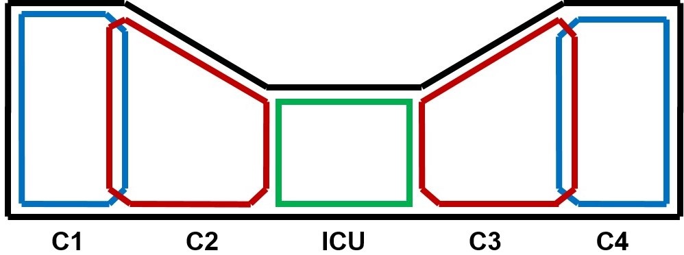
Coil designThe schematic diagram of our proposed inductive coupling neck coil is shown in Fig. 1. Four conventional channels are located on the left and right sides of the neck coil, the resonance frequency of these 4 channels (denoted as C1, C2, C3 and C4, from left to right) is set to 127.8 MHz based on the Larmor frequency of 1H proton at 3.0T. We added an inductive coupling unit (ICU) in the middle of the neck coil to expand the coverage of anterior neck. In addition, the coupling frequency of ICU was designed to be adjustable for further investigation. In addition, the gain of the preamplifier needs to be adjusted to the appropriate range to avoid its self-excitation and to ensure the stability of the coil.
Phantom studies
All imaging tests were carried out on a Philips 3.0T Achieva scanner.
The feasibility and effectiveness of ICU were studied on a cylinder phantom first. Then the optimal coupling frequency was determined by measuring the SNR and comparing the images acquired at different coupling frequencies (127.8 MHz, 131.5 MHz and 135.1 MHz). These same imaging tests were repeated after ICU was removed.
In addition, the coupling cross-talks between conventional channels and ICU were further investigated by phantom experiments. Only one conventional channel was turned on at a time during this experiment.
Furthermore, some clinical routine sequences (T1W FFE, T1W TSE, T2W FFE and T2W TSE) were scanned on an ACR phantom to validate the efficacy of ICU.
In vivo studies
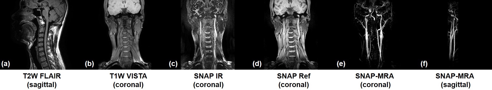
The constructed 4-channel neck coil was combined with a homemade 16-channel head coil and a homemade 12-channel chest coil for in vivo studies. Intra- and extra-cranial imaging were performed on a healthy volunteer using the combined coil. 2D sagittal T2W FLAIR image (TE/TI/TR=133/2000/6000 ms, resolution=1.0*1.0*3.0 mm3, FOV=320*320 mm2), 3D T1W VISTA image (TE/TR=29/600 ms, FOV=320*320 mm2, 0.8 mm3 isotropic resolution) and 3D SNAP image (TE/TR=4.8/10 ms, Flip angle=11°, TI=500 ms, FOV=320*320 mm2, 0.8 mm3 isotropic resolution) were acquired.
This study was approved by the Institutional Review Board and written informed consent was obtained from the participant.
Results and Discussion
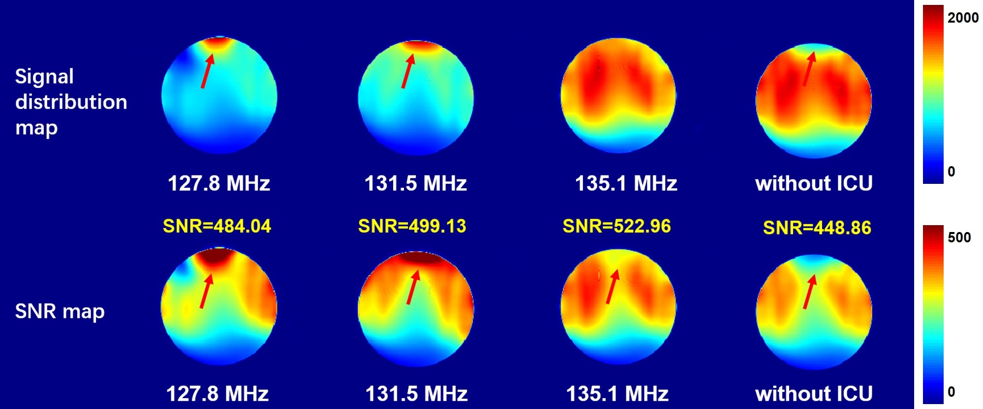
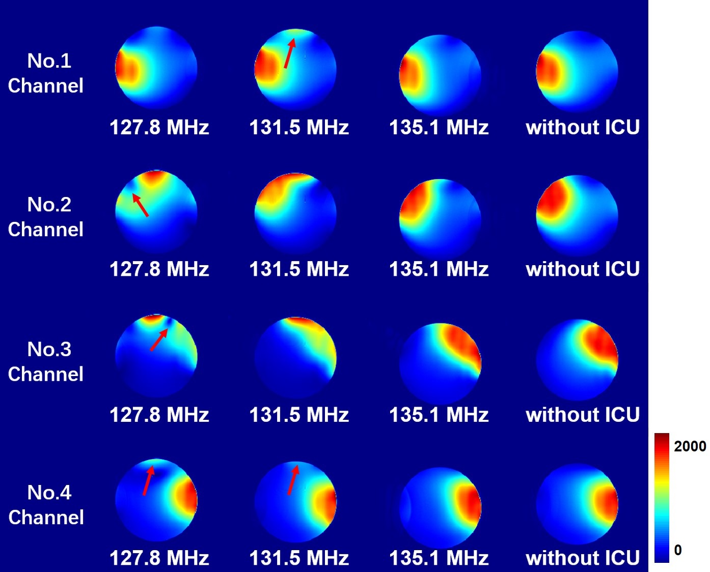
The signal distribution map and SNR map of the images acquired at different coupling frequencies and without ICU are shown in Fig. 2. The introduction of ICU significantly changed the signal distribution. The signal and SNR in the anterior section were greatly improved. However, the quality and uniformity of the image obtained at the inappropriate coupling frequency (127.8 MHz and 131.5 MHz) were degraded. The signal concentrated at the coupling site because of the coupling cross-talk between the ICU and the conventional channels. As such, ICU at the proper coupling frequency (135.1 MHz) can effectively expand the coverage and increase SNR by 16.5%.The ICU is located between C2 and C3. The coupling effect is expected to occur only when C2 and/or C3 are turned on. As shown in Fig. 3, at the improper coupling frequency (127.8 MHz, 131.5 MHz), the coupling phenomenon also appeared when only remote C1 or C4 worked, which indicated that there were signal interferences between the ICU and the 1st and 4th channels. Additionally, the coupling effect even affected the normal usage of the conventional 4 channels. In contrast, at the appropriate coupling frequency (135.1 MHz), the ICU worked well when C2 and/or C3 were turned on, and no unwanted interfering signals were generated, which demonstrated that the coupling strategy is beneficial for expanding the coverage of neck coil effectively.
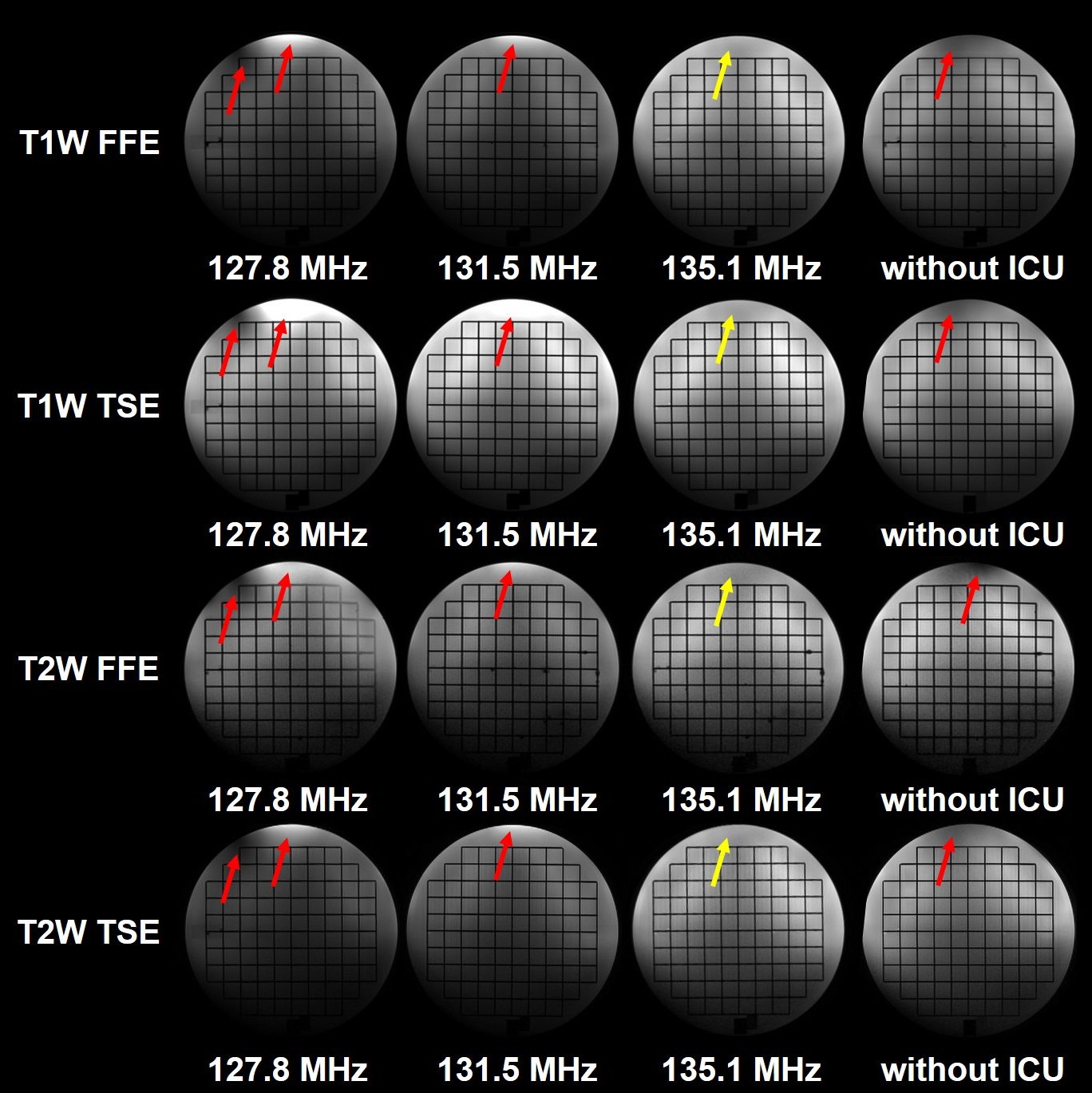
More phantom experiment results are shown in Fig. 4. The images of some clinical routine sequences (T1W FFE, T1W TSE, T2W FFE and T2W TSE) validated the effectiveness of ICU. The new neck coil has the capability to expand the effective coverage and improve the uniformity of the images.
The developed neck coil can be flexibly combined with the homemade head coil and chest coil. The combined coil was used for in vivo intra- and extra-cranial imaging without any interference (Fig. 5) .
Conclusion
In this work, an inductive coupling neck coil was developed and evaluated, it can effectively cover a wider imaging coverage and improve the performance over conventional neck coil. The image obtained at the appropriate coupling frequency (135.1 MHz) has better uniformity and 16.5% higher SNR using the constructed neck coil. Furthermore, the developed neck coil can be flexibly combined with other coils for routine scan without any interference.Acknowledgements
No acknowledgement found.References
1. Gruber B, Froeling M, Leiner T, et al. RF coils: A practical guide for nonphysicists [J]. Journal of Magnetic Resonance Imaging, 2018, 48(3): 590-604.
2. Lee R F, Giaquinto R O, Hardy C J. Coupling and decoupling theory and its application to the MRI phased array [J]. Magnetic Resonance in Medicine, 2002, 48(1): 203-213.
3. Yan X, Gore J C, Grissom W A. Self-decoupled radiofrequency coils for magnetic resonance imaging [J]. Nature communications, 2018, 9(1): 3481.
Figures