4028
Multilayer Radiofrequency Coils: A Novel Surface Coil Design for Improved B1+ Efficiency and Signal-to-Noise1Department of Physiology, Anatomy and Genetics, University of Oxford, Oxford, United Kingdom, 2Oxford Centre for Clinical Magnetic Resonance Research, University of Oxford, Oxford, United Kingdom, 3Department of Physics, University of Oxford, Oxford, United Kingdom, 4PulseTeq LTD, Chobham, United Kingdom
Synopsis
Surface transmitters are often B1+ limited for X-nuclear applications due to hardware limitations of broadband power amplifiers. For both X-nuclear MRI and proton MRI, improved signal detection is always desired. Commonly, signal is measured using surface radiofrequency loop coils or coil arrays. We propose a novel surface coil design using stacked copper layers from one continuous track for increased magnetic flux and sensitivity over a central region of the coil. ‘Multilayer’ designs promise increased B1+ efficiency and Signal-to-Noise, seen using electromagnetic simulations and verified experimentally when compared to conventional loop coils over a range of diameters.
Introduction
The signal, and consequently the diagnostic value, of an MRI scan is, in part, determined by transmit and receive radiofrequency (RF) chain performance. Conventionally, proton MRI possess capable transmit but is limited by the signal-to-noise ratio (SNR), originating from insufficient coil sensitivity in the receive chain. Multi-nuclear imaging, however, is further limited by inadequate magnetic field (B1+) delivery, arising from broadband power amplifier hardware limitations on the transmit chain.Methods
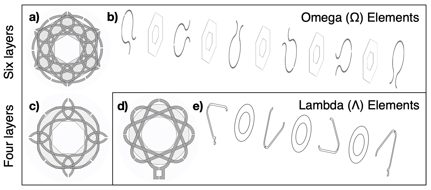
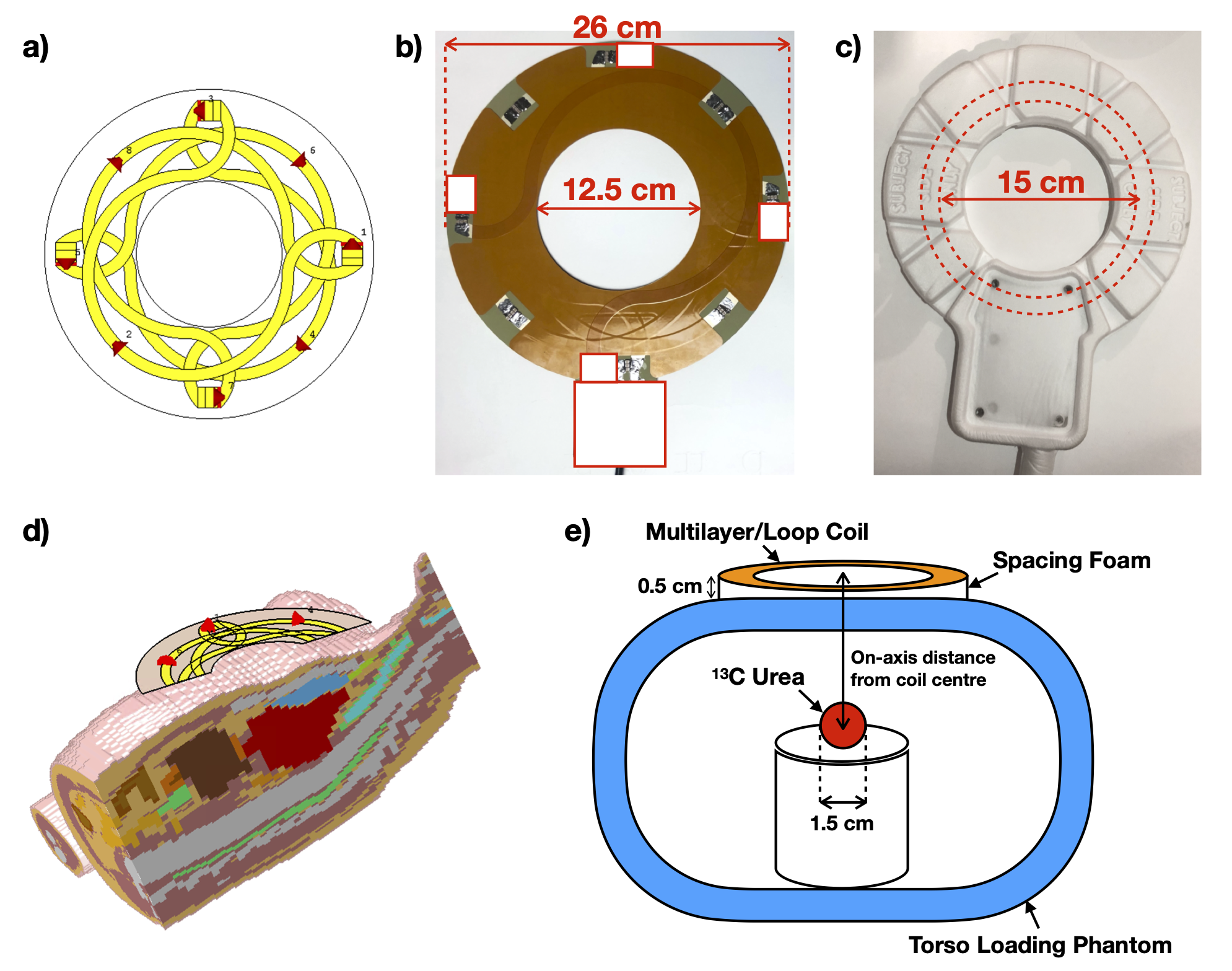
The proposed multilayer designs consist of multiple stacked layers formed from one continuous copper track, rotated about a central axis to enclose a central region, that exhibits increased total magnetic flux contribution compared to a single loop. Differing from a solenoid or concentric ring design1, each conductive layer is rotated about a central-axis to minimise the conductor overlap, and reduce undesired shielding effects from neighbouring layers in close proximity2 (Fig.1). The layered structure exhibits high inductance, leading to greater Q-factor values and inductive coupling to the sample.We previously reported a transmit-receive (Tx/Rx) ‘star’ shaped multilayer design with improved transmit and receive performance compared to two single loop coils for preclinical 23Na MRI (79MHz)3. Here, we present a second iteration comprising a clinical-sized Tx/Rx multilayer coil for 13C at 3T (30.99MHz). This novels design features a four-layer ‘petal’ shape (Fig.2a, 2b) with the addition of curved edges to minimise SAR hotspots and flexibility to allow conformity around the torso. Electromagnetic (EM) simulations were used to determine appropriate loop coil diameters for comparison, as B1+ and SNR field profiles differ according to coil diameter4. Two simulated ‘petal’ multilayer coils [larger coil: inner-diameter=12.5cm, outer-diameter=26cm; smaller coil: inner-diameter=8cm, outer-diameter=22cm] were compared to conventional loop coils with a range of diameters from 5cm to 30cm, placed over a human voxel model, ‘Hugo’ (Fig.2d).
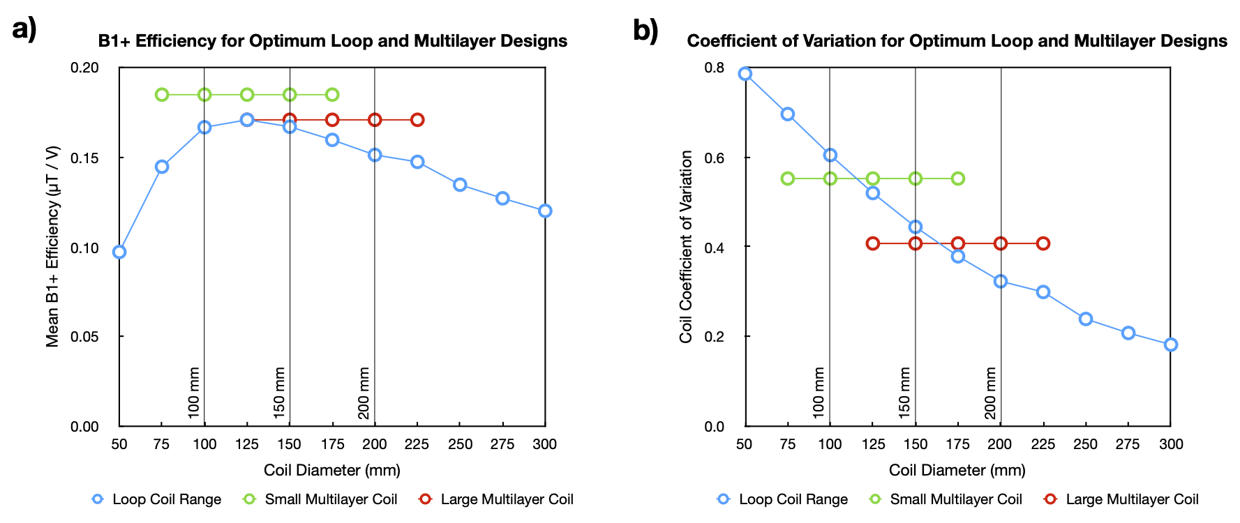
EM simulations were performed on CST Studio Suite (Dassault Systemes, France), using a Finite Difference Time Domain (FDTD) solver and hexahedral meshing (~3 million mesh cells). B1+ fields were exported into MATLAB (MathWorks, MA, USA) at 2mm resolutions. Simulated transmit performance was compared for both multilayer coils and all loop coils, taken as a combination of two metrics summed over all heart voxels: 1. Mean B1+ field over the heart, and 2. B1+ homogeneity, represented as the coefficient of variation (CV), calculated as the B1+ standard deviation normalized by mean B1+.
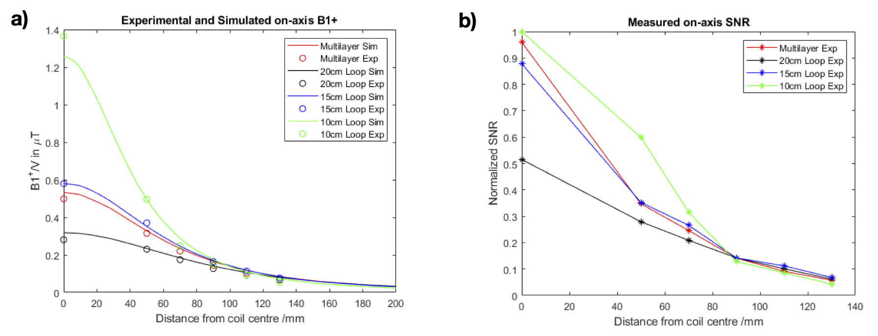
Following these simulations, the larger multilayer design was constructed on a printed circuit board (PCB) (Fig.2b); transmit and receive performance were compared with three single loop coils of diameter 10cm, 15cm (Fig.2c), and 20cm, constructed on PCBs supplied by PulseTeq Ltd (Chobham, UK). On-axis B1+ and SNR were measured using a spherical 8M [13C]urea fiducial, 1.5cm diameter, placed inside a cylindrical hollow torso loading phantom at adjustable depths from the coil centre (Fig.2e). A series of non-localised spectra (pulse-acquire, fully relaxed 5s TR, 2ms rectangular RF pulses) were acquired at increasing voltages to capture the well-known sinusoidal relationship between voltage and signal. The ball was then moved on-axis away from the coil centre at 2cm intervals. SNR (taken as the peak signal divided by standard deviation of noise) and B1+/V (related to the voltage required to achieve 90° excitation) were determined via sinusoidal curve-fit in MATLAB.
Results
EM-simulations showed a maximum averaged B1+ over the heart was achieved using a 12.5cm diameter loop coil (Fig.3a), at the expense of B1+ homogeneity as represented by a higher CV (Fig.3b). The larger multilayer coil (Fig.3, red) demonstrated a compromise between B1+ efficiency and B1+ homogeneity. As such, the multilayer coil achieved a similar mean B1+ as the peak B1+ from the 12.5cm loop coil, but with a 27.6% lower CV equating to significantly improved homogeneity. The second (non-optimized) smaller multilayer coil (Fig.3, green) showed the capability for the multilayer design to achieve 8.2% greater B1+ efficiency than the maximum B1+ possible with a loop coil, whilst exhibiting comparable homogeneity.With the prototype of the larger multilayer coil, B1+ and SNR were measured experimentally against the on-axis distance from coil centre (Fig.4a, 4b). Simulated on-axis B1+ is overlaid onto experimental values taken at 0, 5, 7, 9, 11 and 13cm showing good agreement. The smallest 10cm diameter coil exhibited the highest B1+ efficiency at shallow depths (less than 1 coil diameter) with a steeper drop off in B1+. In keeping with the simulation results, the larger multilayer coil showed similar on-axis B1+ to the 15cm loop and significantly higher B1+ to the 20cm loop. The multilayer design also indicates comparable on-axis SNR with the 15cm loop, with a 6.2% SNR increase at 0cm.
Discussion and Conclusion
EM-simulations showed that the multilayer design had an increased mean B1+ and improved B1+ homogeneity over the heart voxels when compared to a 15cm loop, with good agreement of on-axis B1+ drop off with experiments. Notably, the on-axis SNR performance of the multilayer coil is greater than the on-axis B1+ performance, indicating merit for the multilayer design to be used in a receive only configuration. Further work will involve optimizing the multilayer design, investigating element designs, number of layers, and SAR. We hope to test other nuclei including proton, and multiple multilayer loops in Tx/Rx quadrature and receive only array configurations.Acknowledgements
The authors would like to acknowledge the following funding sources: the Medical Research Council (MRC), the British Heart Foundation (BHF), the National Institute for Health Research (NIHR), Novo Nordisk, and industrial partner PulseTeq Ltd.References
[1] El‐Sharkawy, A. , Schär, M. , Ouwerkerk, R. , Weiss, R. G. and Bottomley, P. A. (2009), Quantitative cardiac 31P spectroscopy at 3 Tesla using adiabatic pulses. Magn. Reson. Med., 61: 785-795. doi:10.1002/mrm.21867
[2] Celozzi, S. and Araneo, R. (2005). Electromagnetic Shielding. In Encyclopedia of RF and Microwave Engineering, K. Chang (Ed.). doi:10.1002/0471654507.eme094
[3] T. Zhou, et al. ISMRM #2520 (2019)
[4] Kumar, A. , Edelstein, W. A. and Bottomley, P. A. (2009), Noise figure limits for circular loop MR coils. Magn. Reson. Med., 61: 1201-1209. doi:10.1002/mrm.21948
Figures