4027
A 4-Channel Conformal Hybrid Coil Array for Rat Limb Imaging at 7T1Center for Advanced Imaging Innovation and Research (CAI2R), NYU School of Medicine, New York, NY, United States, 2Center for Biomedical Imaging, Department of Radiology, NYU School of Medicine, New York, NY, United States
Synopsis
We aim to image the rat limb in longitudinal follow up studies using contrast agents at 7T. Consistent positioning and a high and uniform SNR is required over the ROI. Commercial surface coil arrays offer a high SNR close to the surface but are difficult to position and have poor penetration. Therefore we decided to design a dedicated coil array taking into account the animal's anatomy. We optimized the design in simulations, compared it to a commercial surface coil array in a phantom, and show first in-vivo images.
Introduction
We aim to image the rat limb in longitudinal follow up studies using contrast agents at 7T [1]. Reproducible positioning and a high and uniform SNR over the region-of-interest (ROI) is crucial. Commercial surface coil arrays offer a high SNR close to the surface but are difficult to position and have poor penetration. Furthermore, imaging of both knees requires the repositioning of the coil array.We therefore decided to design a dedicated receive coil array taking into account the animal's anatomy. We optimized the coil design in simulations, compared it to a commercial surface coil array in a phantom, and show first in-vivo images.
Methods
The rat limb, unlike the human knee, is not free standing, see Fig1a, excluding a birdcage design. Therefore a surface coil design is necessary for a high SNR. For reproducible positioning in follow-up studies we designed a U-shaped conformal coil former that holds the knee in place. Hybrid arrays consisting loop and butterfly are ideal candidates offering an intrinsic decoupling on the given U-shaped former.Hybrid coils were identified as potential array candidates for the optimal design in simulations [2]. The boundary conditions for the optimization were the placement of the coil conductors on the coil former for high SNR and a length of 35mm along z to illuminate the whole ROI (white box Fig1a). Optimization goals were a high and reasonably uniform SNR distribution across the ROI. The SNR of small animal coils is not easily assessed in simulation [3]. Due to the small loading factor, the losses in the matching network, capacitors and coil conductors are critical but not easily captured in simulations.
For a better SNR estimate of the coil array candidates we evaluated their virtual SNRs based on experimentally measured SNR maps of the single elements that the array candidates are comprised of, see Fig1c. The candidate array SNRs are emulated by combing the experimental SNR maps in a sum-of-squares fashion, assuming perfect decoupling. The SNR was evaluated over the ROI in a phantom filled with tissue simulating liquid mimicking the rat's limb, see Fig1b.
A winning candidate, based on the virtual SNR maps, was identified and built, see Fig3. The coil conductors were routed on a flexible PCB and wrapped on the U-shaped 3D-printed coil former. Copper wires were used for overlaps. The elements were matched to the optimal preamplifier noise impedance of 50 Ohms. Active detuning is achieved by switching a PIN diode that forms an open circuit at the coil port. The MR signal is amplified by a low noise preamplifier on a seperate PCB and the coil is interfaced with an ODU plug to the MR system.
We compared the SNR of the hybrid coil array in the phantom to a commercial surface 2x2 loop array (1P T11483V3, Bruker BioSpin MRI, Ettlingen, Germany). Finally, in-vivo SNR of the rat limb were acquired and the SNR-maps were computed according to [4].
The MR images in Figs4,5 were aquired using a 7T BioSpec micro-MRI system (Bruker BioSpin MRI, Ettlingen, Germany). A quadrature birdcage coil was used for transmission (112/086 1H QTR, Bruker BioSpin MRI, Ettlingen, Germany).
Results and Discussion
The SNR-maps in the central transversal plane of the single coil element candidates can be seen in Fig1c. The winning hybrid coil array is shown in Fig3. It is a combination of a short and thin loop and a short butterfly coil (L2 and BF1, see Fig1c), yielding a hybrid element array segmented in z-direction to cover the ROI, see Fig3a,b.Compared to the commercial surface coil the dedicated limb coil array offers a slightly higher SNR close to the surface in peripheral slices and slightly lower in the central slice. Furthermore, the SNR is more uniform resulting in a higher SNR in deeper regions. The limb coil array was invisible during transmission, offering a uniform transmit field.
A preliminary in-vivo SNR map of the rat limb is shown in Fig5. It shows a uniform and high SNR across the ROI.
Conclusion
A dedicated receive coil array for rat limb imaging at 7T was optimized, constructed and successfully tested. The conformal coil former allows for reproducible positioning and the hybrid conformal coil array offers a higher and more homogeneous SNR as compared to a commercial rat head surface coil array.The results presented for one knee are convincing encouraging us to extend the coil array for both knees doubling the throughput.
Acknowledgements
The Authors would like to thank Stephen J. Dodd for his advice on coil design, and Youssef Zaim Wadghiri for his support.References
1. Ruiz, A., Duarte, A., Milne, M., Bravo, D., Luyt, L., Raya, J. (2018),Imaging low-grade inflammation in post-traumatic osteoarthritis, Osteoarthritis and Cartilage, Volume 26, S44 - S45
2. J. Paska, A. Ruiz, J. Raya, Fast Optimization Method for RF Coil Array Geometry in a Post-Processing Step, ISMRM, Intl Soc. Mag. Reson. Med..p.4401, Paris, France, June 2018.
3. F. D. Doty, G. Entzminger, J. Kulkarni, K. Pamarthy, J. P. Staab (2007), Radio frequency coil technology for small animal MRI, NMR in Biomedicine, 20, 304-325.
4. Kellman, P., McVeigh, E. R. (2005). Image reconstruction in SNR units: a general method for SNR measurement. Magnetic Resonance in Medicine, 54(6), 1439–1447. https://doi.org/10.1002/mrm.20713
Figures
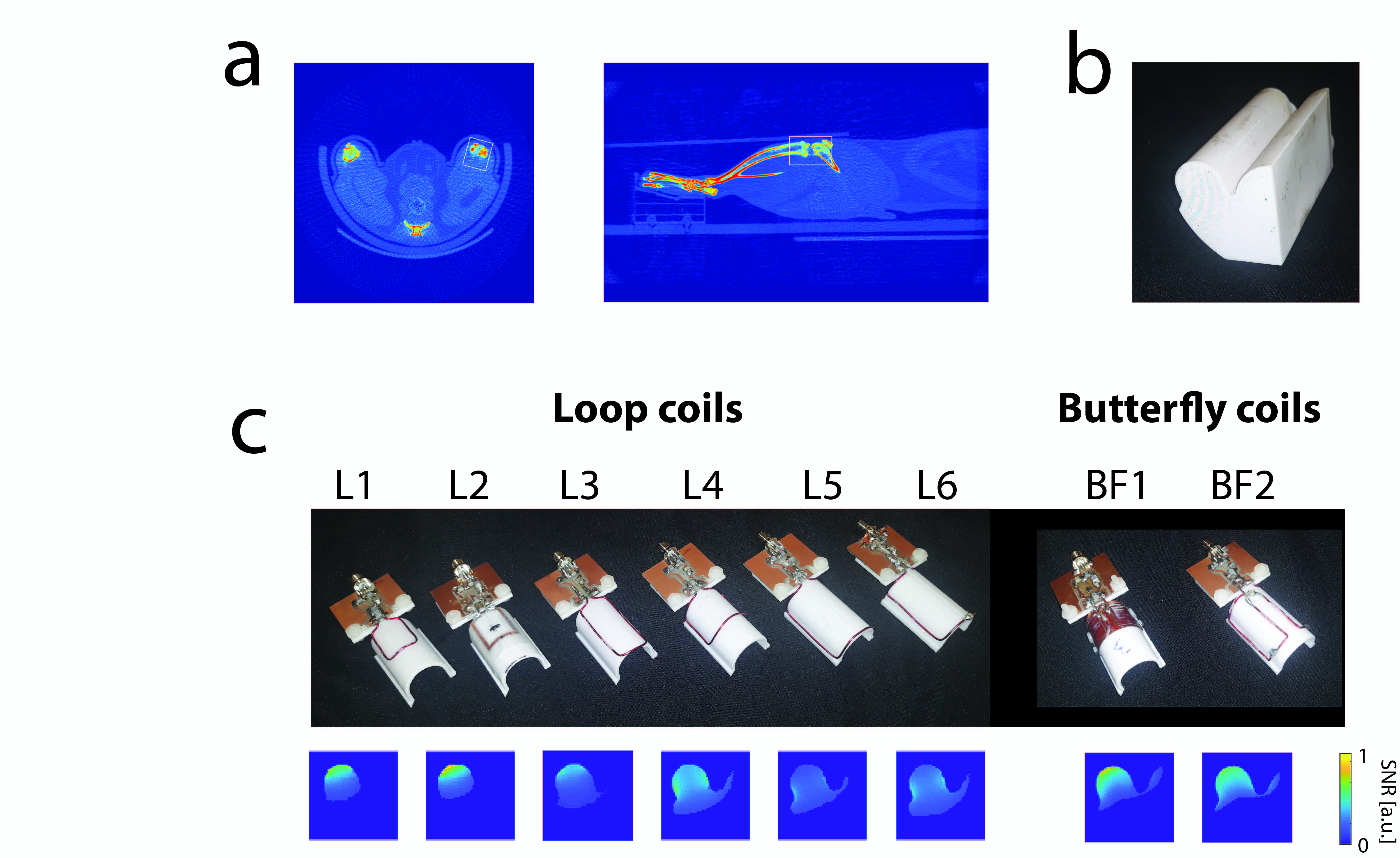
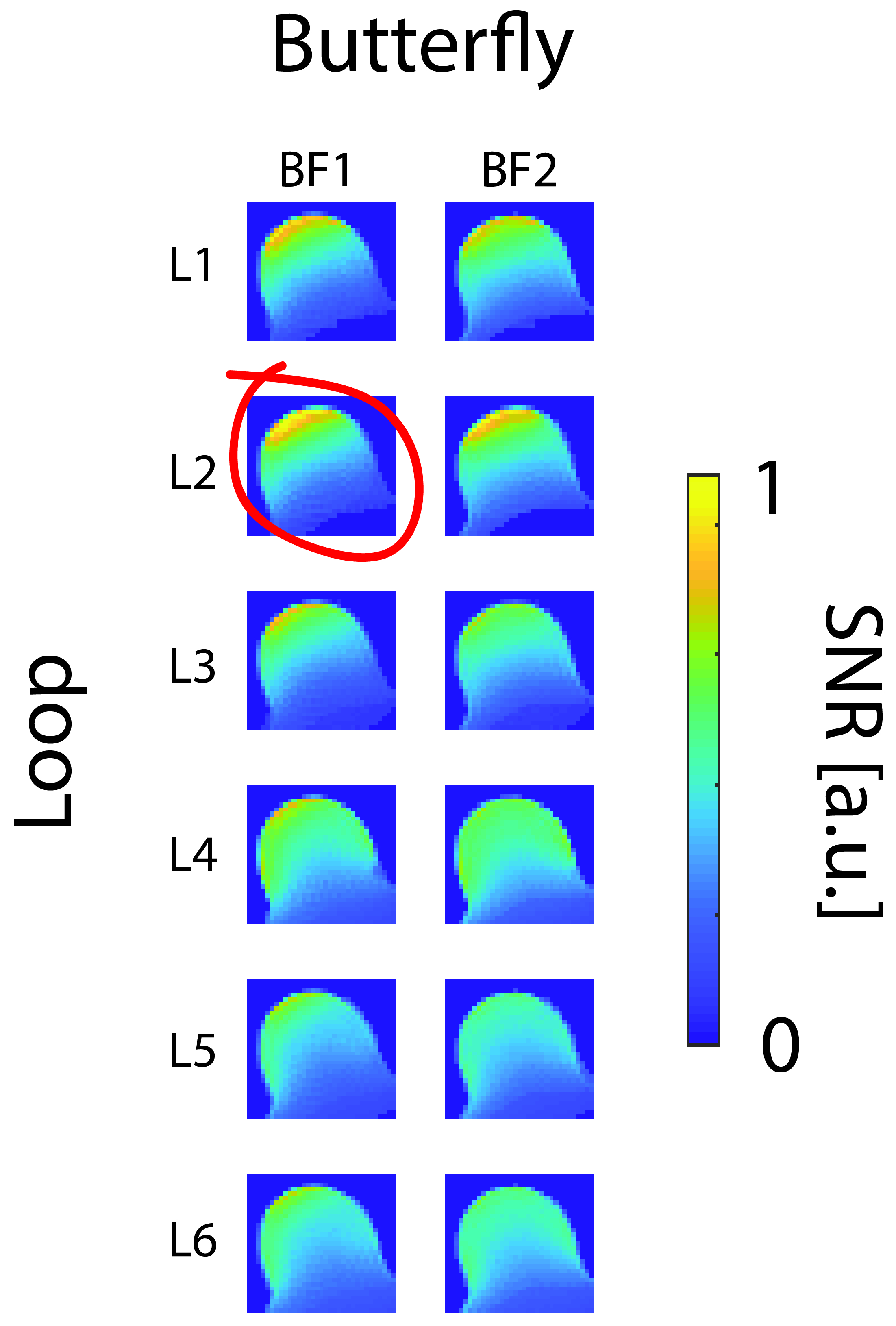
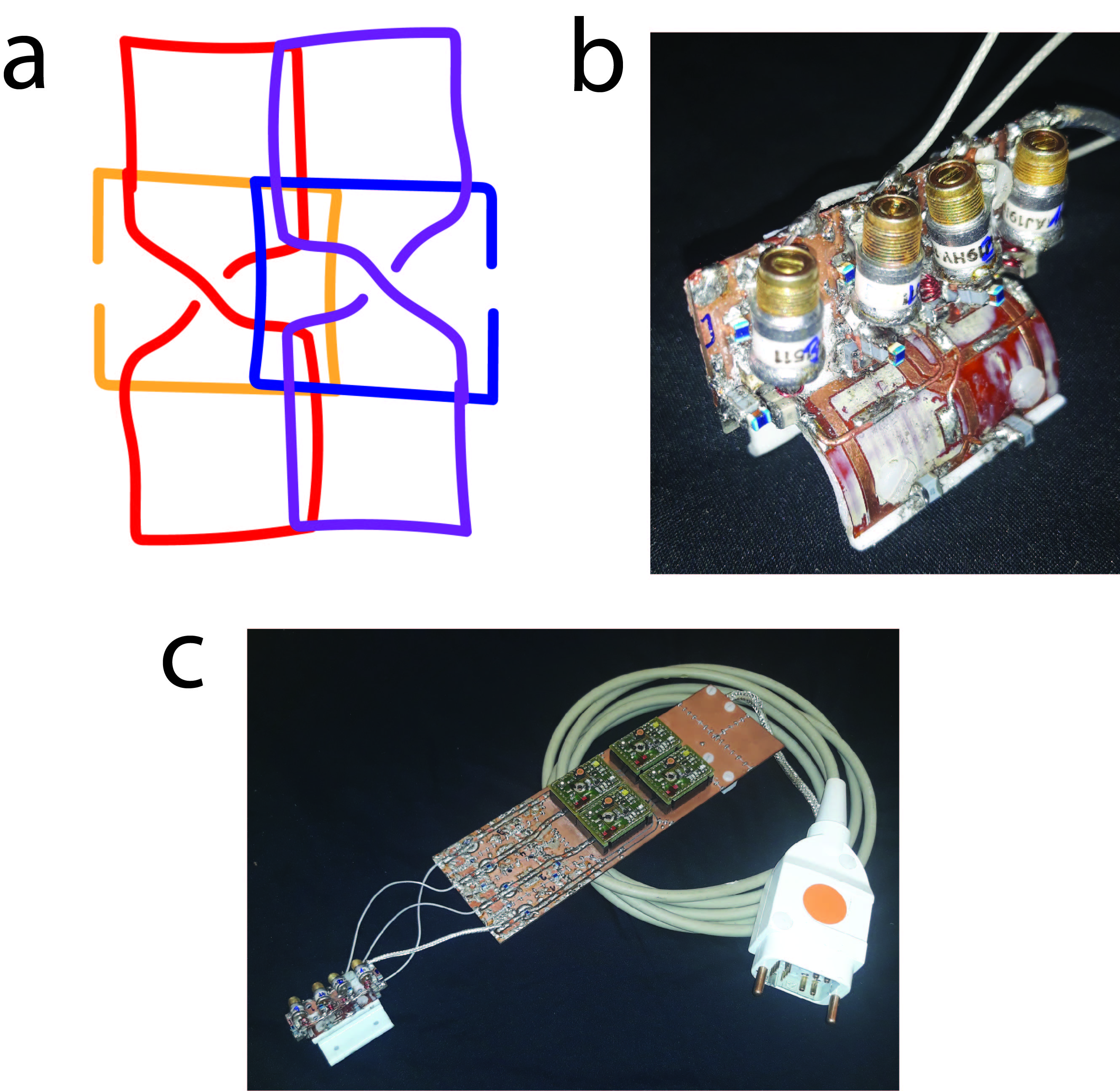
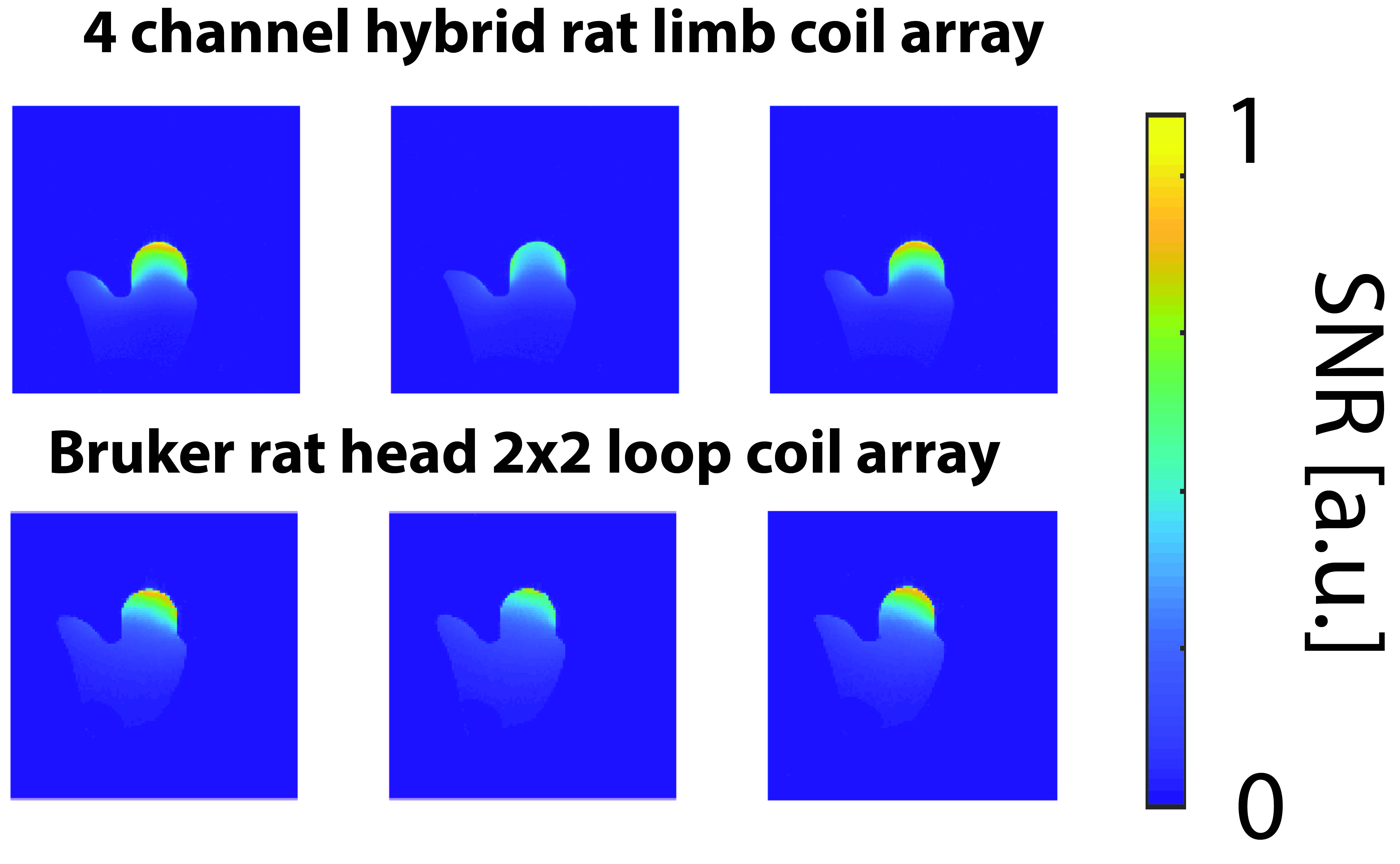
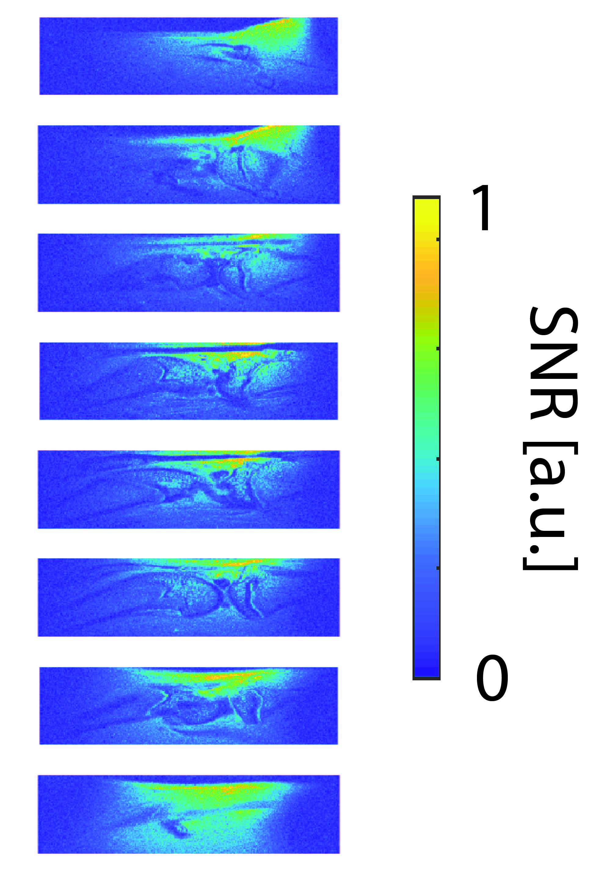
Figure 5: SNR-maps in the rat limb, using the hybrid coil array. Eight sagittal slices across the ROI.
The MR images were acquired on a 7T BioSpec micro-MRI system (Bruker BioSpin MRI, Ettlingen, Germany) using a proton density weighted Turbo Spin Echo (TR=5343ms, TE=12.5s, Turbospinechofactor=5, Echospacing=6.25ms, Res=80x80x750microm, matrix size=270x70, 8 slices)