4024
A 30-Channel Single Layer Transceiver Head Coil at 3.0T
Haoqin Zhu1, Xiaoyu Yang1, Michael Wyban1, Yiping Guan2, and Yoshinori Hamamura2
1Quality Electrodynamics, LLC (QED), Mayfield Village, OH, United States, 2Canon Medical Research USA, Inc, Mayfield Village, OH, United States
1Quality Electrodynamics, LLC (QED), Mayfield Village, OH, United States, 2Canon Medical Research USA, Inc, Mayfield Village, OH, United States
Synopsis
A novel open design 30ch transceiver head coil without using a local RF power source is proposed. Each coil element has no detuning circuit, couples to the system whole body coil inductively, and generates a uniform B1+ field in transmit mode. The same coil element also acts as a typical phased array element in receive mode. The transceiver feature of the coil may benefit the SAR demanding simultaneous multi-slice (SMS)/multi-band (MB) and high-resolution imaging and still keep the clinical friendly openings. In addition, the same coil element approach simplifies the coil circuit and improves the signal-to-noise ratio (SNR).
Introduction
Compared with a receive-only head coil a transmit/receive (Tx/Rx) head coil has an advantage of exciting head only without exciting higher SAR shoulder if the whole-body-coil (WBC) is used. This is important for SAR demanding simultaneous multi-slice/multi-band and high-resolution imaging. Additionally, the head coil openings are extremely important for minimizing claustrophobic reactions. However, the existing methods of transceiver phased array coils1,2,3,4 require complicated electronics and additional Tx coil on top of the receiver elements. It becomes difficult or impossible for a Tx/Rx head coil having openings as large as an Rx-only coil using the existing methods. This abstract proposes an open design 30-ch single layer transceiver (SLT) head coil without using additional Tx coil at 3T. This study extends the previous work5 to the head imaging.Methods
The proposed SLT head coil is a 30-channel array coil. It generates a uniform local B1+ field by allowing each channel coupling to the WBC inductively in Tx mode. It works like a typical array coil in Rx mode. Because the head coil is smaller and closer to the head, the induced B1+ field at head is much larger than the B1+ at other areas, such as shoulder. Thus, it acts as a local Tx/Rx coil at the head. The size and shape of the head coil were optimized for fitting 95th percentile US male as shown in Fig.1. The inner dimensions are 205 mm in Left-Right direction, 243 mm in Anterior-Posterior direction and 262mm in Head-Foot direction. The coil has three rows and 10 channels/row. The typical channel size is about 100mm X 110mm. The coil copper is 3mm wide. A typical schematic is shown in Fig.2. In Tx mode all diodes are forward biased. L1 and C5 form a resonant circuit and generate a high impedance to block the preamplifier from the coil at the 3T frequency. This enables the coil Q high. D2 provides additional protection to the preamplifier. Then all channels couple to the WBC inductively. This allows a uniform local B1+ field generated inside the coil. In order to achieve a high B1+ uniformity and efficiency, each channel’s resonant frequency in Tx must be tuned independently by adjusting C6 so that the combined B1+ field from all channels is uniform. In Rx mode, all diodes are backward biased and the whole coil works as a phased array coil. The system SAR control for this coil was done by implementing a set of coil file parameters. This is similar to a local Tx/Rx head coil SAR control. All images were acquired from a Canon Galan 3T MRI system. Both phantom (Polyvinyl Alcohol) and volunteer images were collected. A commercial 32-ch head Rx-only phased array coil (Quality Electrodynamics) was also scanned for SNR comparison. The commercial 32-ch Rx-only head coil has a similar inner dimension as the proposed 30-ch transceiver head coil.Results
The WBC-only transmit power gain for the phantom is 47.9dB. The WBC and SLT head coil Tx gain is 39.9dB for the same phantom in Tx mode. The SLT head coil requires 8 dB lower Tx power. A commercial single-channel QD head coil (Quality Electrodynamics) was evaluated for the Tx power comparison. It is a 16-rung birdcage coil with a 27cm diameter and a 27cm length. Its Tx power gain is about 8.3 dB lower than the WBC-only transmit gain. In Rx mode The SLT coil element / ranges from 2.6 to 3 on the workbench. The comparison 32-ch Rx only coil / ranges from 1.6 to 2.2. An SNR comparison test was performed on the phantom using the system standard spin-echo sequence. The 30-channel SLT head coil shows an average 18% SNR increases at the center. The phantom and volunteer images of both coils are shown in Fig.3 and Fig.4 respectively.Discussions
The proposed SLT head coil has a similar Tx power requirement as a Tx/Rx QD head coil by using the inductive coupling between the SLT head and the WBC. The SLT head coil amplifies the B1+ field inside the head coil due to its much smaller size than the WBC. Because the SLT head coil doesn’t need to detune in Tx mode, the Rx coil Q reduction from the detuning circuit doesn’t exist anymore. This results in an SNR boost. This is one of the contributors from the / and the SNR boost we observed. As shown in Fig.1 all openings from Rx-only coil can be conserved due to no additional layer Tx coil. Last but not the least the novel SLT approach provides an MR system cost saving by not providing local Tx power source while still keeping an equivalent local Tx/Rx coil capability.Conclusions
We demonstrated a novel approach to build a transceiver phased array head coil at 3T. The Tx efficiency of the proposed coil is similar to a local Tx/Rx QD head coil. The approach enables a local Tx function for the high channel count head coil without sacrificing coil opening. In addition, the novel approach may also improve SNR performance due to no detuning coil Q loss.Acknowledgements
No AcknowledgementsReferences
- X. Yang, et al, Proc. Intl. Soc. Mag. Reson. Med. 13, 907, 2005
- Seunghoon Ha, Haoqin Zhu, Labros Petropoulos, Proc. Intl. Soc. Mag. Reson. Med. 23 (2015)
- W. Wang, et al, Proc. Intl. Soc. Mag. Reson. Med. 18 1510, 2010
- Nikolai I. Avdievich et al, Magnetic Resonance in Medicine 76:1621–1628 (2016)
- X. Yang, et al, Proc. Intl. Soc. Mag. Reson. Med. 26, 2018
Figures

Fig.1
30-channel single layer transceiver phased head
coil
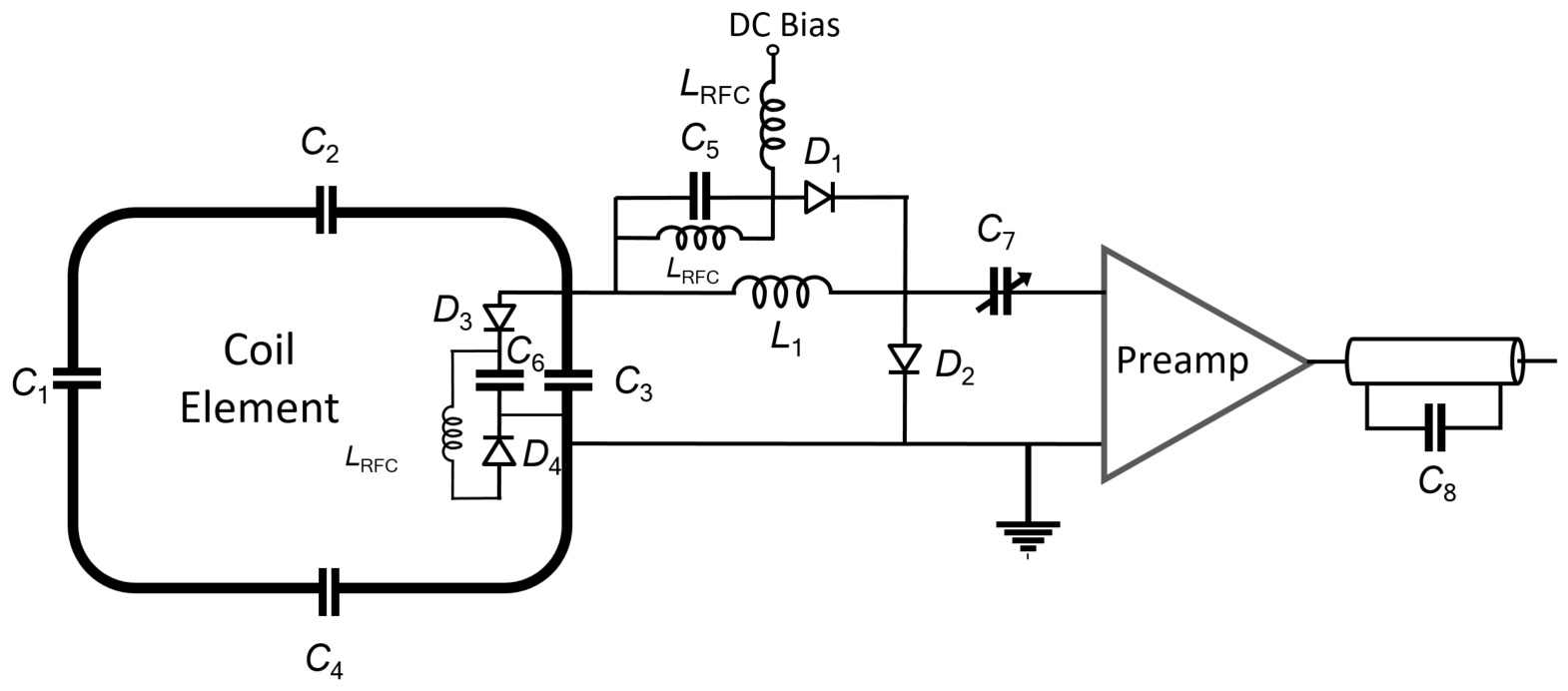
Fig.2 Coil
element schematic
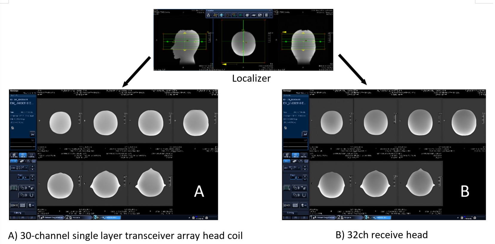
Fig.3 Phantom image: 30-channel single layer
transceiver array head coil vs 32ch receive head coil
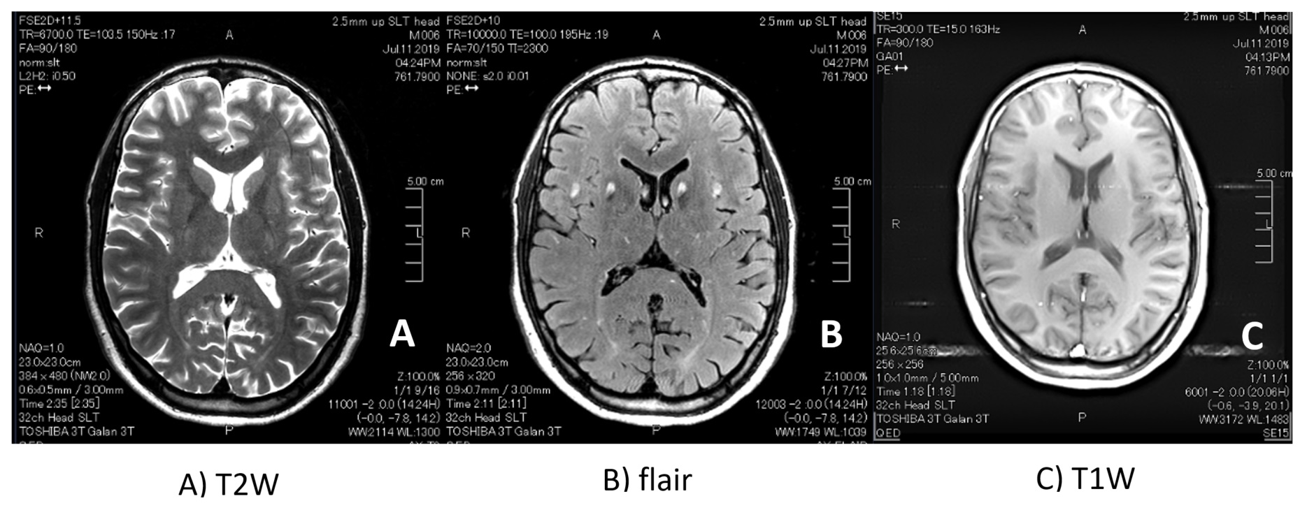
Fig.4 Volunteer image with 30-channel single layer
transceiver array head coil