4022
Development and RF Shimming of an 8Tx/16Rx Antisymmetric Transceiver Coil Array for Parallel Transmit Cardiac MRI in Humans at 7T1Chair of Cellular and Molecular Imaging, Comprehensive Heart Failure Center (CHFC), University Hospital Wuerzburg, Wuerzburg, Germany
Synopsis
To develop and optimize an 8Tx/16Rx antisymmetric transceiver coil array with improved characteristic for static phase $$$B_1^+$$$-shimming and parallel receive for human cardiac MRI at 7T. The array design was based on antisymmetric loop configurations in 2-different directions (L/R and A/P). EM-simulations were carried out in phantom and 4-human models (Duke, Ella, Gustav, and Laura). $$$B_1^+$$$-shimming has been carried out for 16-elements with three different cost functions to improve $$$B_1^+$$$-field homogeneity, $$$Tx_{eff}$$$ and weighted combination of both within Duke and Ella models. The hardware and imaging performance of the antisymmetric array was validated through EM-simulations and phantom MR-measurements at 7T.
Introduction
With ultrahigh field (UHF) strength ($$$B_{0}$$$≥7T) magnetic resonance imaging (MRI) scanners, a significant improvement in the SNR, and hence in spatial and temporal resolutions can be achieved compared to conventional lower field strength ($$$B_{0}$$$≤3T). At 297.2-MHz, the RF-wavelength in biological tissues is ~12cm, which approaches or becomes shorter than the dimensions of the object to be imaged (here the heart). Despite the numerous technical challenges related to $$$B_{0}$$$ and $$$B_1^+$$$-field inhomogeneities for cMRI at 7T, the application of UHF scanners for cardiovascular research holds significant promise. Continued hardware developments in RF-coil arrays have allowed significant progress for body imaging at UHF (e.g., stripeline resonators1, 2 Tx/Rx loops3–6, dipoles7–9, and combined dipoles/loops10, 11). The magnitude and phase of the signal of each individual transmit coil element can be optimized (RF-shimming) to provide a uniform combined $$$B_1^+$$$-field distribution within the heart region-of-interest (ROI)12, 13. The pTx-system allows for driving the individual 8Tx-channels of the array dynamically (i.e. to vary the magnitude/phase of each channel). $$$B_1^+$$$-shimming of an 8Tx/16Rx pTx antisymmetric cardiac array was described. The array consistis of 2-sections, a curved anterior section to conform to an average human torso and an identical planar posterior section, each array comprised of 8-elements14. The hardware and imaging performance of the developed human array was validated through EM-simulations and phantom MR-measurements at 7T.Methods
For $$$B_1^+$$$-shimming and 10g averaged SAR calculations, EM-simulations were carried out using CST-Microwave-Studio. RF-circuit co-simulation was employed for good matching, tuning, and decoupling at 297.2-MHz15. The antisymmetric array (Fig. 1b&c) was loaded with an elliptical phantom ($$$\epsilon_{r}$$$=59.3 and $$$\sigma$$$=0.79S/m) and 4-human voxel models (Duke and Ella) from IT’IS Foundation and (Gustav and Laura) from CST with 2.0×2.0×2.0mm3, 2.0×2.0×2.0mm3, 2.08×2.08×2.0mm3 and 1.875×1.875×1.25mm3, resolutions, respectively. The total numbers of mesh cells are 62.765, 56.885, 49.507, and 42.916 million for Duke, Ella, Gustav, and Laura, respectively. The local 10g SAR was computed using the IEEE/IEC-62704-1 method. Static phase $$$B_1^+$$$-shimming was carried out to achieve the optimal $$$B_1^+$$$-field homogeneity within a 3D-ROI (10x10x8cm3) within the heart. The optimization algorithm provided the optimal phase vector (PV) for the 16-element array by solving the following three optimization cost functions ($$$F_{c1}$$$, $$$F_{c2}$$$ and $$$F_{c3}$$$):$$F_{c1}=\frac{[mean(B_1^+)]^2}{std(B_1^+)(max(B_1^+)-mean(B_1^+))}TXE (1)$$
$$F_{c2}=\frac{min(B_1^+)\cdot TXE}{std(B_1^+)} (2) $$
$$F_{c3}=w\cdot F_{c1}+\sqrt{(1-w^2)}F_{c2}, where, w = 0.8 (3)$$
$$TXE=\frac{\sum_k^Nb_{1,k}^+(\phi_k)}{\sum_k^N|b_{1,k}^+|} (4)$$
$$\{{\phi_k}\}=argmax[F_{c(1-3)}(\{{\phi_k}\})] (5)$$
$$B_{1}^+=\sum_{k=1}^N{b_{1,k}^+(\phi_k)} (6)$$
$$RSD=\frac{std(B_1^+)}{mean(B_1^+)}(7)$$
$$SAR_{eff}=\frac{mean(B_1^+)}{\sqrt{SAR_{10g,max}}}(8)$$
$$Tx_{eff}=\frac{mean(B_1^+)}{\sqrt{p_{in}}}(9)$$
$$FoM=\frac{mean(B_1^+)}{RSD\sqrt{SAR_{10g,max}}}(10)$$
where, RSD, $$$Tx_{eff}$$$ and FoM are relative-standard-deviation, transmit efficiency and Figure-of-Merit, respectively.
The optimization was performed for Duke and Ella human models to provide the optimal vectors (PV1, PV2 and PV3) and applied for the Gustav and Laura. PV1 was found using the cost function $$$F_{c1}$$$ providing maximum $$$B_1^+$$$-field homogeneity within Duke model. PV2 was found using the cost function $$$F_{c2}$$$ to achieve minimal destructive interference effects (“maximal minimum” principle) within Duke model. PV3 was found using weighted combination of both $$$B_1^+$$$-field homogeneity and $$$Tx_{eff}$$$ using cost function $$$F_{c3}$$$ within Ella model. The antisymmetric cardiac array was interfaced to the 7T system in the sTx mode to validate the two best optimal phase vectors (PV2 and PV3) and compared to a commercial 1Tx/16Rx 16-channel transceiver array (MRI.Tools GmbH, Berlin, Germany). Combinations of coaxial RF cable phase shifters with different lengths (22.5°, 45°, 90°, and 180°) were used. To investigate the potential benefit of the antisymmetric array in $$$B_1^+$$$-shimming of both magnitudes/phases using the 7T pTx system, phantom MR-measurements were performed and compared to a prototype 8Tx/16Rx pTx cardiac human array (Rapid Biomedical GmbH, Rimpar, Germany).
Results and Discussion
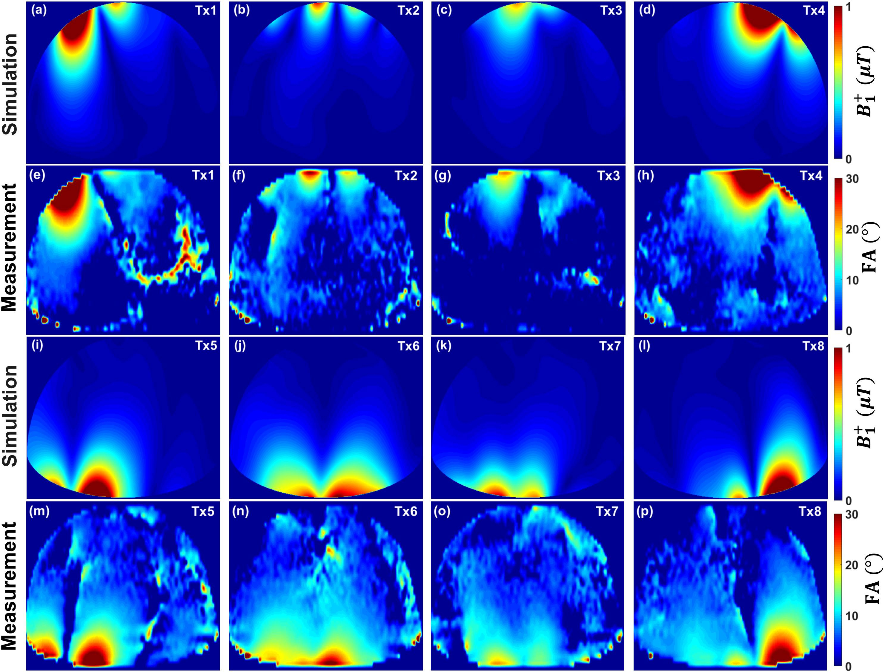
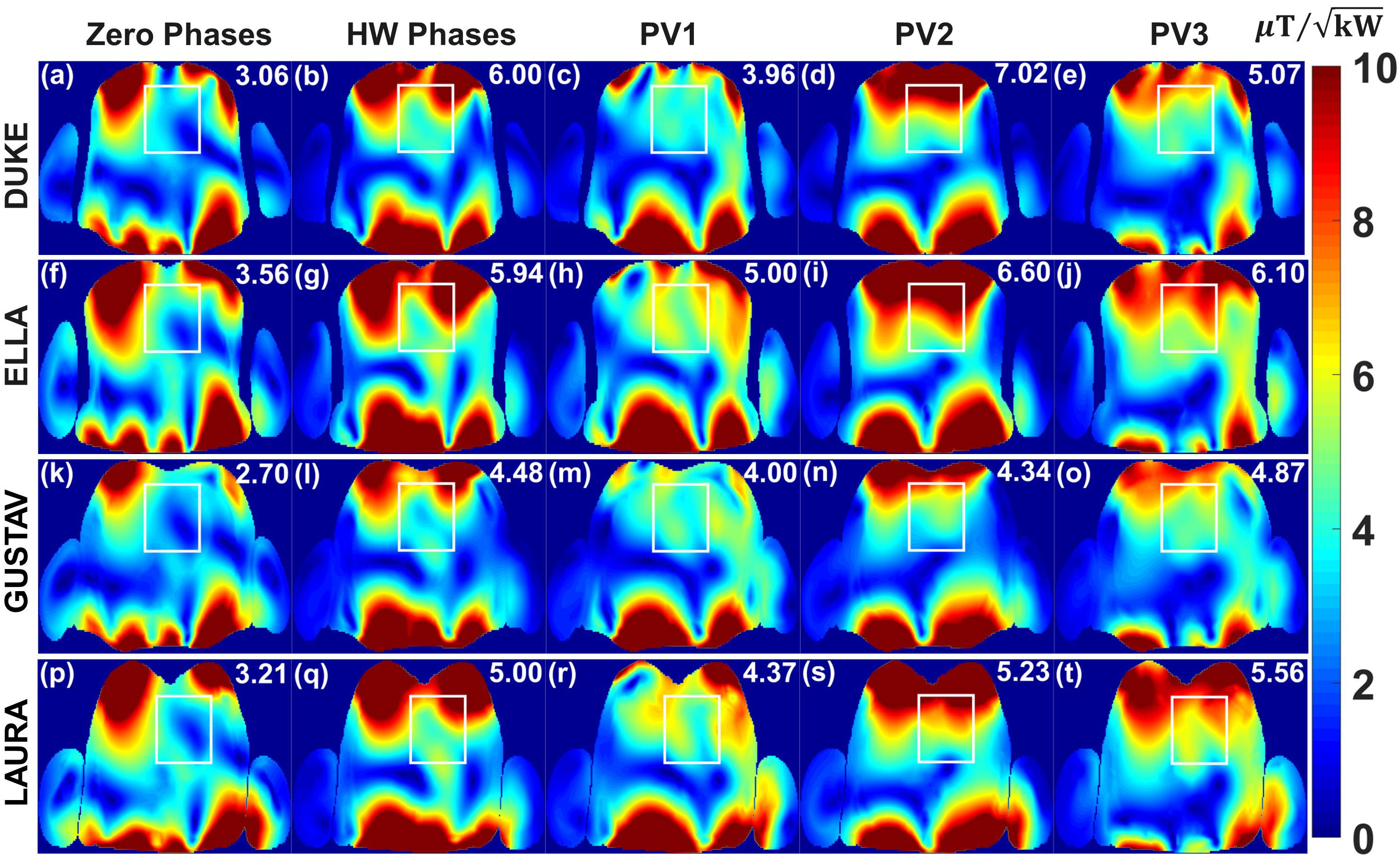
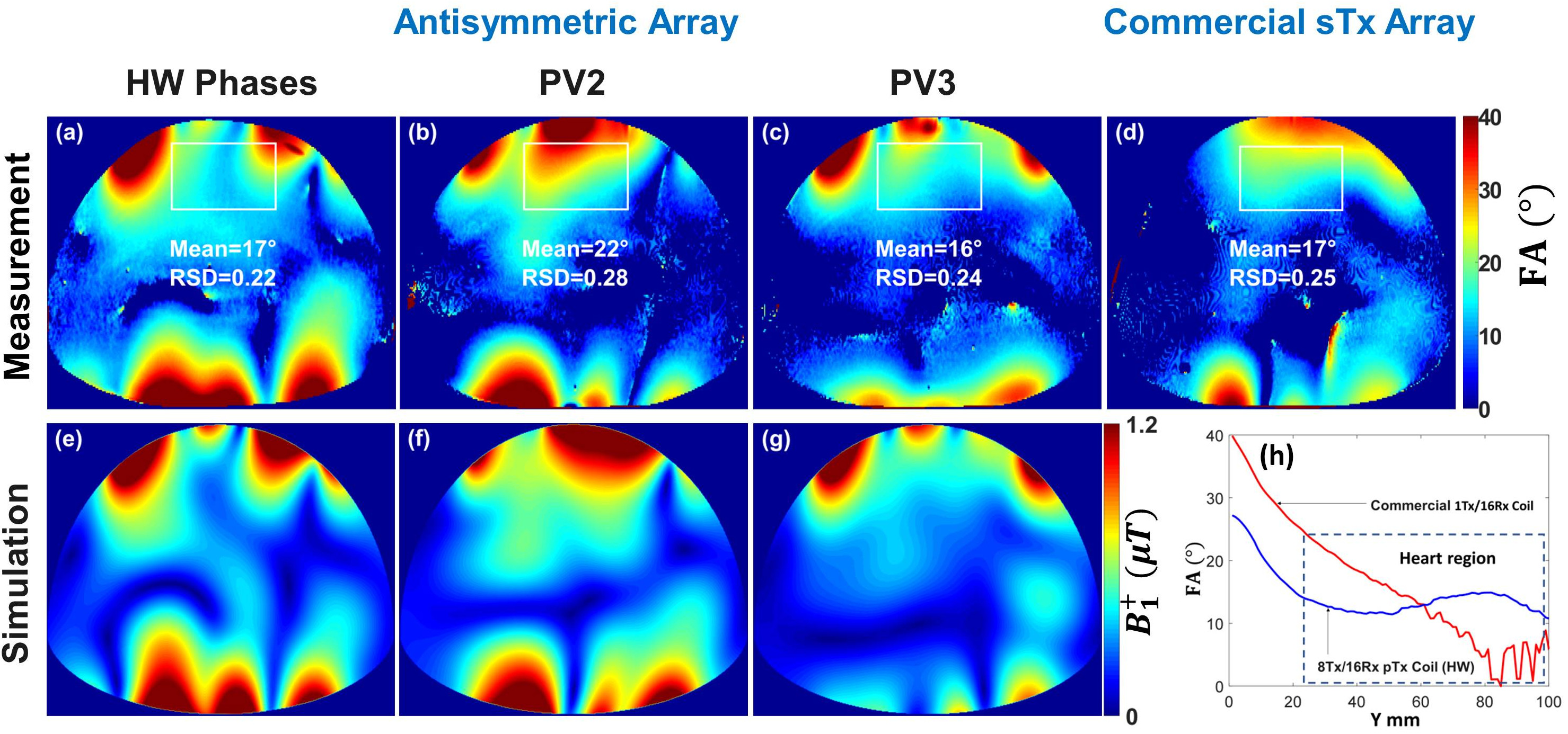
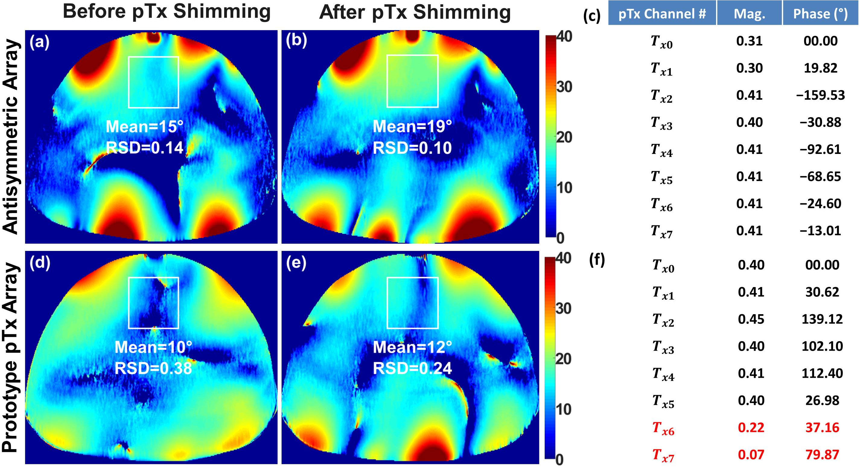
Fig. 2 illustrates the simulated central transversal $$$B_1^+$$$-field distribution and measured FA-maps within the phantom for the individual 8Tx-channels ($$$T_{x1}$$$-$$$T_{x8}$$$). It can be seen that the antisymmetric array generates spatial $$$B_1^+$$$-field distribution appearing for all 8Tx-channels. Good agreement between simulated $$$B_1^+$$$-field distributions and the experimentally measured FA-maps was achieved for the channels ($$$T_{x1}$$$, $$$T_{x2}$$$, $$$T_{x3}$$$, $$$T_{x4}$$$, $$$T_{x5}$$$, and $$$T_{x8}$$$). However, there were some differences in measured FA-maps for $$$T_{x6}$$$ and $$$T_{x7}$$$ (Fig. 2j,k,n,o). Fig. 3 displays the simulated combined central transversal $$$B_1^+$$$-field within the Duke, Ella, Gustav, and Laura human models with zero phases, HW phases, PV1, PV2 and PV3. Phase $$$B_1^+$$$-shimming with PV3 has the potential to improve $$$Tx_{eff}$$$ by factor >60% for the 4-human models, respectively, compared to zero-phases. The maximum local 10g SAR values were found to be 6.60, 5.73, 4.69, 3.74, and 5.98W/kg for zero phases, HW phases, PV1, PV2, and PV3, respectively, given the same stimulated power of 8W. Fig. 4a-h demonstrates the simulated combined central transversal $$$B_1^+$$$-field and measured FA-map for HW phases, PV2 and PV3 compared to a commercial 1Tx/16Rx transceiver array. Fig. 5 illustrates the measured combined central FA-map before and after pTx $$$B_1^+$$$-shimming compared to a prototype 8Tx/16Rx pTx transceiver array. The pTx-shimming enhanced the mean FA by about 30% in the selected ROI (50x50x10mm3). The antisymmetric array allows for shaping a relatively homogeneous profile of the FA to the full depth of the heart.Conclusion
The antisymmetric L-shaped elements arrangement scheme implemented in the developed human cardiac array demonstrated a significant advancement in $$$B_1^+$$$-field homogeneity and RF-shimming capability within Duke and Ella models. The improved performance of $$$Tx_{eff}$$$ and $$$SAR_{eff}$$$ were validated in 4-human models, which proves the high potential of the antisymmetric design for pTx Tx/Rx arrays.Acknowledgements
This project is funded by the German Ministry of Education and Research (BMBF) with grant # 01EO1004 & 01EO1504.References
- C.J. Snyder et al., Initial results of cardiac imaging at 7 Tesla, Magn. Reson. Med. 61 (3) (2009) 517–524.
- J.T. Vaughan et al., Whole-body imaging at 7T: preliminary results, Magn. Reson. Med. 61 (1) (2009) 244–248.
- A. Graessl et al., Modular 32-channel transceiver coil array for cardiac MRI at 7.0T, Magn. Reson. Med. 72 (1) (2014) 276–290.
- M.A. Dieringer et al., Design and application of a four-channel transmit/receive surface coil for functional cardiac imaging at 7T, J. Magn. Reson. Imag. 33 (3)(2011) 736–741.
- A. Gräßl et al., Design, evaluation and application of an eight channel transmit/receive coil array for cardiac MRI at 7.0T, Eur. J. Radiol. 82 (5) (2013) 752–759.
- C. Thalhammer et al., Two-dimensional sixteen channel transmit/receive coil array for cardiac MRI at 7.0 T: design, evaluation, and application, J. Magn Reson Imag. 36 (4) (2012) 847–857.
- C. Oezerdem et al., 16-channel bow tie antenna transceiver array for cardiac MR at 7.0 tesla, Magn. Reson. Med. 75 (6) (2016) 2553–2565.
- A.J.E. Raaijmakers, P.R. Luijten, C.A. van Den Berg, Dipole antennas for ultrahigh-field body imaging: a comparison with loop coils, NMR Biomed. 29 (9) (2016) 1122–1130.
- M.A. Ertürk et al., Toward imaging the body at 10.5 tesla, Magn. Reson. Med. 77 (1) (2017) 434–443.
- M.A. Ertürk, A.J. Raaijmakers, G. Adriany, K. Ug˘urbil, G.J. Metzger, A 16-channel combined loop-dipole transceiver array for 7 T esla body MRI, Magn. Reson. Med. 77 (2) (2017) 884–894.
- B.R. Steensma et al., An 8-channel Tx/Rx dipole array combined with 16 Rx loops for high-resolution functional cardiac imaging at 7 T, Magn Reson Mater Phy 31 (1) (2018) 7–18.
- W. Mao, M.B. Smith, C.M. Collins, Exploring the limits of RF shimming for high field MRI of the human head, Magn. Reson. Med. 56 (4) (2006) 918–922.
- C.M. Collins, W. Liu, B.J. Swift, M.B. Smith, Combination of optimized transmit arrays and some receive array reconstruction methods can yield homogeneous images at very high frequencies, Magn. Reson. Med. 54 (6) (2005) 1327–1332.
- I. A. Elabyad et al., Development of asymmetric 8Tx/16Rx coil array for human cardiac MRI at 7 T: RF shimming and SAR safety study, Proc 27th Intl. Soc. Mag. Reson. Med. (ISMRM), Montreal, Canada, p.6150, 2019.
- M. Kozlov, R. Turner, Fast MRI coil analysis based on 3-D electromagnetic and RF circuit co-simulation, J. Magn Reson 200 (1) (2009) 147–152.
Figures
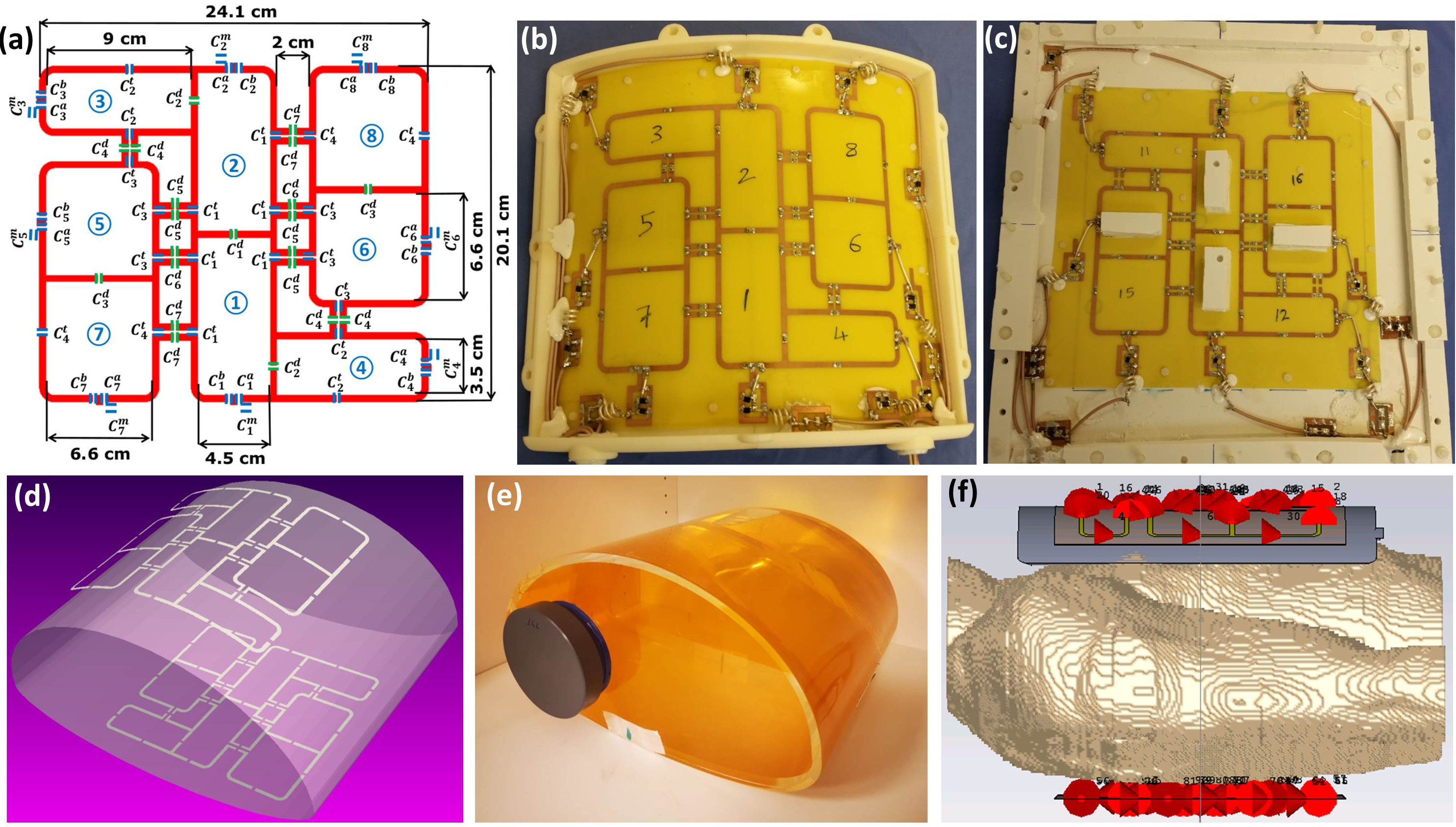
Figure 1 Schematic of the antisymmetric array with element dimensions, capacitor variables, and channel numbers14 (a), anterior array prototype (b) posterior array prototype (c). RF simulation model loaded with an elliptical human body phantom (d), the in-house developed human body phantom (e), the human voxel model Duke (f). The variable names for the capacitors are: m for matching, t for tuning, d for decoupling and a, b for splitting tuning.