4021
A Mono-surface 8Tx/16Rx Antisymmetric Dipole Antenna Array for Parallel Transmit Cardiac MRI in Pigs at 7T
Ibrahim A. Elabyad1, M. Terekhov1, and Laura M. Schreiber1
1Chair of Cellular and Molecular Imaging, Comprehensive Heart Failure Center (CHFC), University Hospital Wuerzburg, Wuerzburg, Germany
1Chair of Cellular and Molecular Imaging, Comprehensive Heart Failure Center (CHFC), University Hospital Wuerzburg, Wuerzburg, Germany
Synopsis
A mono-surface 8Tx/16Rx antisymmetric dipole antenna array was designed and tested for parallel transmit (pTx) cardiac magnetic resonance imaging (cMRI) in pigs at 7T. The antisymmetric array comprised of a mono-surface 16-dipoles arranged so that two central L-shaped dipoles were anti-symmetrically flanked by 7-dipoles on either side. Combined FA, SNR, and g-factor maps were acquired in phantom using the dipole antenna array and compared with an 8Tx/16Rx loop array. After $$$B_1^+$$$-shimming using the dipole array, the SNR was enhanced by ~20% and FA by ~42%. Dipole antenna array has demonstrated ~20-times improvement in RSD of the FA after $$$B_1^+$$$-shimming.
Introduction
Dipole antennas are promising for body imaging at UHF1–6 because they generate a fairly uniform $$$B_1^+$$$-field distribution with higher penetration depth inside the body compared to traditional loops. Thus, dipoles are good candidates for deep seated organs such as the heart. To achieve maximum power transmission efficiency from a dipole antenna, the physical length of the antenna needs to be half-wavelength ($$$\lambda$$$/2) of the RF-frequency in free space. For a straight self-resonant half-wavelength dipole antenna at 7T (297.2 MHZ), this corresponds to a length of ~50cm. These relatively long dipole dimensions impose many constraints for the design of a multi-row dipole antenna array optimized for cMRI in pigs at 7T. The dipole antenna size may be shortened with some loss of transmit efficiency by incorporating lumped element inductors or by employing meander structures. Different types of RF-coil arrays have allowed significant progress for body imaging at UHF (e.g., Tx/Rx loops7–10 and combined dipoles/loops11, 12). RF-shimming can be applied to provide a uniform combined $$$B_1^+$$$-field distribution within the heart region-of-interest (ROI)13, 14 using the pTx system by driving the individual 8Tx-channels of the array dynamically (i.e. to vary the magnitude/phase of each channel). In this work, we report the design and testing of a 16-channel antisymmetric pTx dipole antenna array for pigs at 7T. The antisymmetric dipole configuration was designed to enable $$$B_1^+$$$-shimming and parallel imaging for cMRI in pigs (50-80kg) at 7T.Methods
The antisymmetric dipole antenna array was composed of a mono-surface with 16-dipoles and they were arranged in such a way that each 7-elements are reversed and mirrored around the central two L-shaped dipoles (Fig. 1a). The 14-dipoles were distributed around the central two L-shaped dipoles in an antisymmetric distribution. The effective sizes of dipoles were selected to fit within a half elliptical shape housing (major/minor diameter=34cm/42cm) and to achieve sufficient $$$B_1^+$$$-field penetration at ~10cm depth. The center-to-center horizontal gap distance is 5.5cm for all dipoles. The total external dimension of the array is 26.1cm×61cm. EM-simulations were carried out using CST-Microwave-Studio for array design loaded with a dedicated pig body phantom (height/width=28cm/25cm and length=30cm) ($$$\epsilon_{r}$$$=59.0 and $$$\sigma$$$=0.79-S/m). RF-circuit co-simulation was employed for good matching, tuning, and decoupling at 297.2 MHz. All dipoles have a copper track width of 10mm and a thickness of 35$$$\mu$$$m etched on a 0.3mm FR4-PCB. The PCB is bent around a half-elliptical shape housing of 5mm thickness made from ABS. The antisymmetric dipole antenna array was compared to an 8Tx/16Rx antisymmetric loop array15 in pTx mode. Both arrays have the same housing dimensions and thickness. For each dipole element, two equal series inductors were connected to both arms (Fig. 1c). Each dipole element was matched to 50Ω coaxial cable using two balanced series capacitors and one shunt capacitor. A coaxial cable trap was placed by the discrete phase shifter circuits and matching capacitor for both dipoles and loop arrays to minimize common mode cable currents. Both arrays were tested in phantom MR-measurements using an in-house designed and built pig body phantom (Fig. 1c). Combined FA-maps, SNR-maps, and parallel imaging performance using acceleration factors R=2-6 were assessed. The Relative-Standard-Deviation (RSD)=SD(FA)/Mean(FA). All MR-measurements were performed on a 7T whole-body 7T Siemens Magnetom Terra scanner (Siemens Healthineers, Erlangen, Germany) in pTx mode.Results and Discussion
Fig. 2 demonstrates the measured combined central transversal FA-maps before and after $$$B_1^+$$$-shimming acquired using the dipole antenna and loop arrays. It is of interest to note that pTx $$$B_1^+$$$-shimming using dipole array enhanced the mean FA by ~42% and the RSD by factor >20 in the selected ROI (50x50x10mm3). Dipole antenna array has a relatively homogeneous FA with deeper penetration depth within the heart ROI compared to the loop array. Fig. 3 shows the measured noise correlation matrices and combined SNR-maps before and after pTx $$$B_1^+$$$-shimming acquired using dipole antenna and loop arrays. $$$B_1^+$$$-shimming enhanced the mean SNR of the dipole by ~20%. However, the SNR of the antisymmetric loop array is still ~62% higher than dipole array. Fig. 4 demonstrates the measured g-factor maps of R=2-6 after pTx-shimming acquired using dipole and loop arrays. Parallel imaging with an acceleration factor of R=6 was possible with the loop array while keeping the mean g-factor within the selected ROI at 1.4. However, for dipoles acceleration factor of up to R=4 is still possible. The antisymmetric dipole antenna array exhibited good decoupling between neighboring elements (Fig. 3a). However, dipoles are very sensitive to proximity to the load, exhibiting strong frequency shifts between the pig phantom and a 60kg ex-vivo pig. The 16-dipoles were matched to ~–14 dB with the fixed coil-to-phantom distance of ~1.5cm. The antisymmetric 8Tx/16Rx pTx loop array showed good matching and tuning for both pig phantom and a 60kg ex-vivo pig without frequency shift. The stability of the loop array in terms of tuning/matching, S-matrix, and phase variations along elements is much better than dipoles.Conclusion
The antisymmetric 8Tx/16Rx dipole antenna array has demonstrated a significant improvement in RSD after pTx $$$B_1^+$$$-shimming with about >20-times improvement compared before pTx-shimming. The dipole antenna array has demonstrated good RF-shimming capability provided by antisymmetric 16-dipoles orientations with deeper penetration depth compared to loop array for cMRI at 7T.Acknowledgements
This project is funded by the German Ministry of Education and Research (BMBF) with grant # 01EO1004 & 01EO1504.References
- Raaijmakers AJ, Ipek O, Klomp DW, Possanzini C, Harvey PR, Lagendijk JJ, van den Berg CA. Design of a radiative surface coil array element at 7 T: the single-side adapted dipole antenna. Magn Reson Med 2011;66:1488–1497.
- Raaijmakers AJ, Italiaander M, Voogt IJ, Luijten PR, Hoogduin JM, Klomp DW, van den Berg CA. The fractionated dipole antenna: a new antenna for body imaging at 7 Tesla. Magn Reson Med 2016;75: 1366–1374.
- Ipek O, Raaijmakers AJ, Klomp DW, Lagendijk JJ, Luijten PR, van den Berg CA. Characterization of transceive surface element designs for 7 tesla magnetic resonance imaging of the prostate: radiative antenna and microstrip. Phys Med Biol 2012;57:343–355.
- C. Oezerdem et al., 16-channel bow tie antenna transceiver array for cardiac MR at 7.0 tesla, Magn. Reson. Med. 75 (6) (2016) 2553–2565.
- A.J.E. Raaijmakers, P.R. Luijten, C.A. van Den Berg, Dipole antennas for ultrahigh-field body imaging: a comparison with loop coils, NMR Biomed. 29 (9) (2016) 1122–1130.
- M.A. Ertürk et al., Toward imaging the body at 10.5 tesla, Magn. Reson. Med. 77 (1) (2017) 434–443.
- A. Graessl et al., Modular 32-channel transceiver coil array for cardiac MRI at 7.0T, Magn. Reson. Med. 72 (1) (2014) 276–290.
- M.A. Dieringer et al., Design and application of a four-channel transmit/receive surface coil for functional cardiac imaging at 7T, J. Magn. Reson. Imag. 33 (3)(2011) 736–741.
- A. Gräßl et al., Design, evaluation and application of an eight channel transmit/receive coil array for cardiac MRI at 7.0T, Eur. J. Radiol. 82 (5) (2013) 752–759.
- C. Thalhammer et al., Two-dimensional sixteen channel transmit/receive coil array for cardiac MRI at 7.0 T: design, evaluation, and application, J. Magn Reson Imag. 36 (4) (2012) 847–857.
- M.A. Ertürk, A.J. Raaijmakers, G. Adriany, K. Ug˘urbil, G.J. Metzger, A 16-channel combined loop-dipole transceiver array for 7 T esla body MRI, Magn. Reson. Med. 77 (2) (2017) 884–894.
- B.R. Steensma et al., An 8-channel Tx/Rx dipole array combined with 16 Rx loops for high-resolution functional cardiac imaging at 7 T, Magn Reson Mater Phy 31 (1) (2018) 7–18.
- W. Mao et al., Exploring the limits of RF shimming for high field MRI of the human head, Magn. Reson. Med. 56 (4) (2006) 918–922.
- C.M. Collins et al., Combination of optimized transmit arrays and some receive array reconstruction methods can yield homogeneous images at very high frequencies, Magn. Reson. Med. 54 (6) (2005) 1327–1332.
- I. A. Elabyad et al., A novel asymmetric 16-element pTx transceiver coil array: towards denser elements for improved RF-shimming and g-factor for parallel cardiac MRI in pigs at 7T, Proc 27th Intl. Soc. Mag. Reson. Med. (ISMRM), Montreal, Canada, p.5251, 2019.
Figures
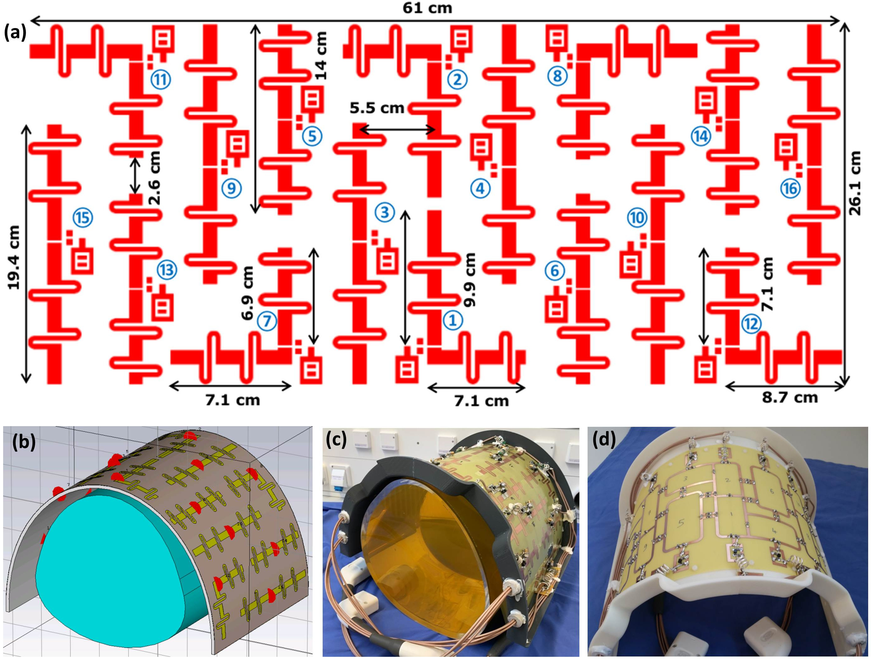
Figure 1 Schematic of
the mono-surface antisymmetric 16-channel dipole antenna array with element dimensions and channel numbers (a), RF simulation model of the array as simulated
in CST-MWS loaded with an in-house designed and built pig phantom (b), prototype of the antisymmetric
8Tx/16Rx pTx
dipole antenna array (c), and prototype
of the antisymmetric 8Tx/16Rx pTx loop array as published in15.
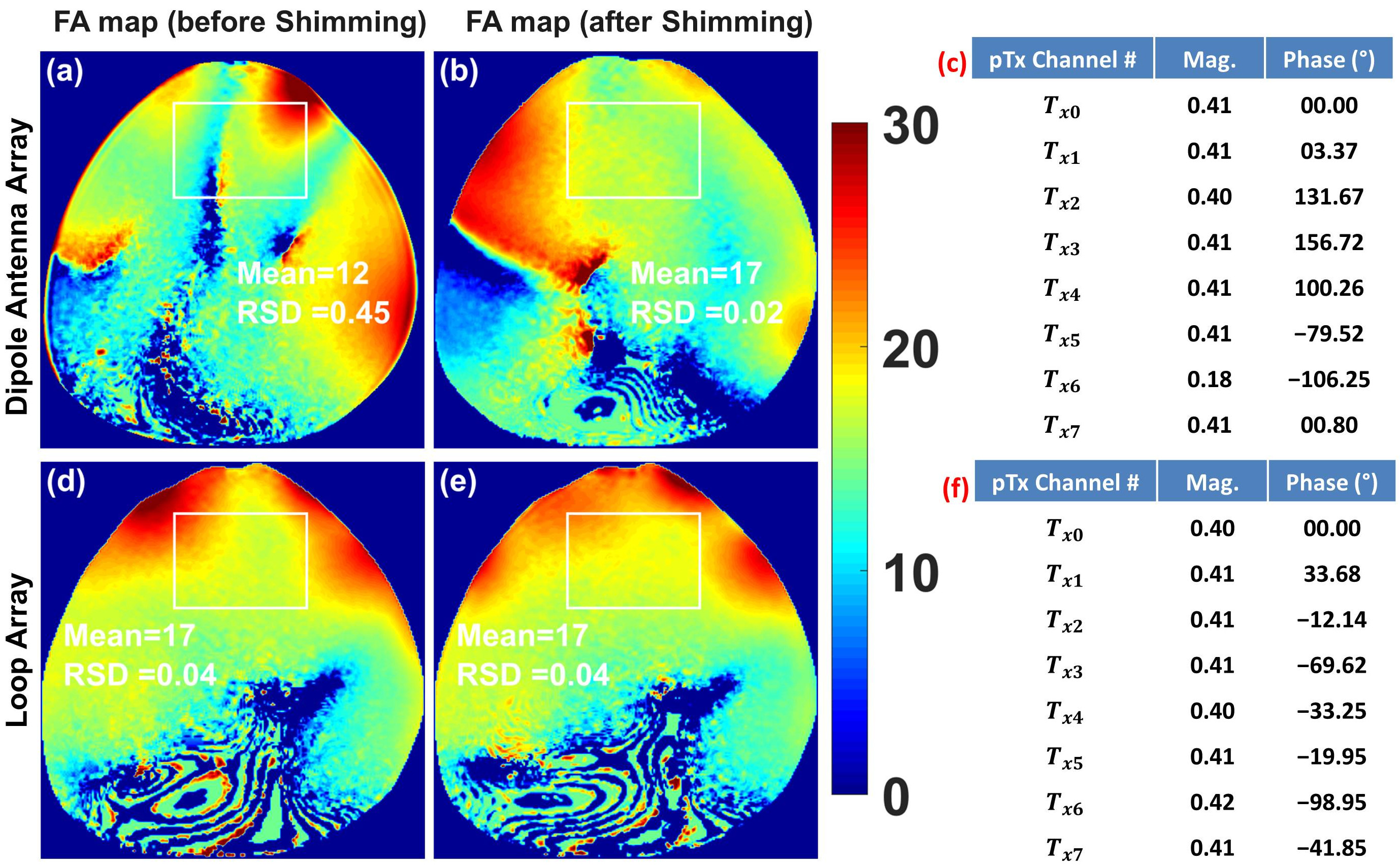
Figure 2 Measured
combined central transversal FA maps in degrees before and after
pTx B1+ shimming acquired using the antisymmetric 8Tx/16Rx dipole antenna array and an 8Tx/16Rx antisymmetric loop array given the computed optimal
amplitudes and phases after pTx shimming obtained using the vendor integrated pTx shimming method.
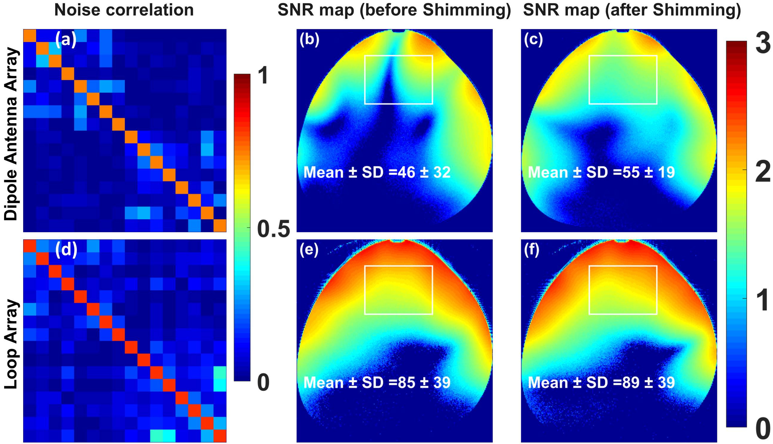
Figure 3 Measured
noise correlation matrix and SNR maps in logarithmic scale before and
after pTx B1+ shimming acquired using the the
mono-surface 16-elements antisymmetric dipole antenna array (first row), and the loop array
(second row) loaded with the same pig phantom. The mean ± SD of SNR in linear units
were computed in the selected ROI.
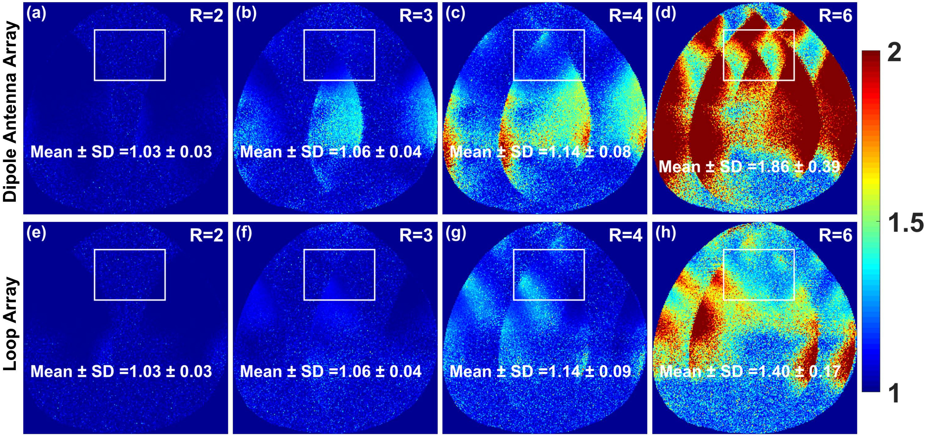
Figure 4 Measured
g-factor maps of R=2, 3, 4, and 6 acquired using the the mono-surface 8Tx/16Rx pTx
antisymmetric dipole antenna array
(first row), and 8Tx/16Rx pTx loop array (second row) loaded with the same pig phantom. The
mean ± SD of g-factor values were computed in the selected ROI.