3712
Feasibility of High-resolution Knee Imaging with A Spiral Dixon Technique1Department of Radiology, Mayo Clinic, Rochester, MN, United States, 2Department of Neuroradiology, Barrow Neurological Institute, Phoenix, AZ, United States, 3Philips Healthcare, Gainesville, FL, United States
Synopsis
In this study, a spiral Dixon technique has been implemented for knee imaging at 3T with high in-plane resolution of up to 0.4 by 0.4 mm2. Volunteer scans have demonstrated that high quality proton density-weighted, T2-weighted and T1-weighted water and fat images can be obtained using spiral spin-echo and dual spin-echo Dixon methods with comparable total scan time as the conventional Cartesian fast (turbo) spin-echo sequences without Dixon. In addition, spiral radial plane imaging can shorten the scan time by 62% compared to the conventional radial plane method.
Introduction
Magnetic resonance imaging (MRI) is a proven noninvasive diagnostic test for the detection, evaluation, assessment, staging, and follow-up of disorders of the knee1. At 3T, high-resolution proton density-weighted (PDW), T2-weighted (T2W) and T1-weighted (T1W) images are often acquired with two-dimensional (2D) fast (turbo) spin-echo (FSE or TSE) sequences at different orientations in routine knee exams1,2. Additional sequences may be used for their sensitivity for specific abnormalities. One example of these sequences is 2D gradient recalled echo (GRE) imaging in radial planes to better detect meniscal disorders3,4. Fat suppression is commonly used in one or more of the sequences to enhance the diagnostic yield, for instance, to identify marrow abnormalities1.Spiral imaging has many favorable characteristics such as fast imaging, high signal-to-noise ratio (SNR) efficiency and low sensitivity to motion. Spiral imaging has been implemented for high resolution brain imaging5-7 along with the advancements in spiral Dixon technique8. The goal of this study is to investigate the feasibility of spiral knee imaging with in-plane resolution as high as 0.4 x 0.4 mm2.
Materials and Methods
Spiral pulse sequences were implemented on a 3T scanner (Ingenia Elition, Philips Healthcare, Best, The Netherlands). Data of four volunteers were collected using a 16-channel knee transmit/receive coil. Informed consent was obtained in accordance with the guidelines of the institutional review board. Sagittal PDW, sagittal T2W, coronal T1W and radial plane images were acquired. For all fully sampled spiral scans, data were acquired at each nominal echo time (TE) with two TE shifts, 0 and 1.15 ms, for Dixon water-fat imaging. Field maps of the static field inhomogeneity were obtained from separate low-resolution Cartesian scans, with which water and fat images were reconstructed using a joint water-fat separation and deblurring method8. Cartesian scans with parameters close to the clinical routine knee exams were also performed for comparison. Some of the scan parameters are summarized in Table 1.Sagittal PDW and T2W imaging
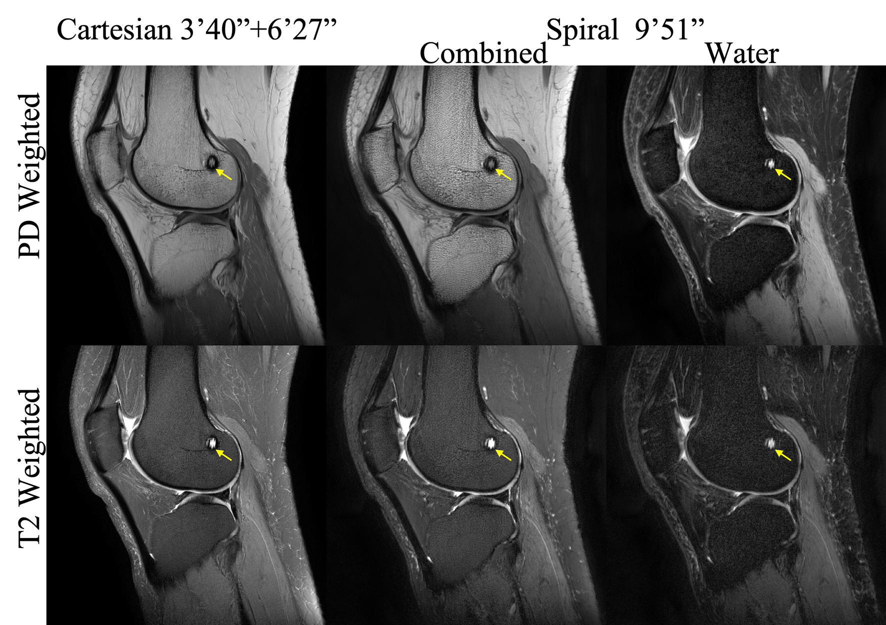
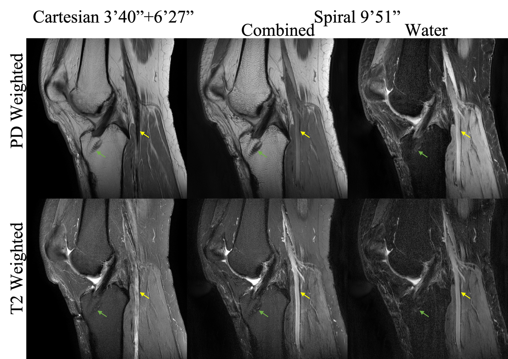
A 2D dual spin-echo (SE) technique with hybrid spiral readouts was used to simultaneously collect data for PDW and T2W at the first echo and the second echo respectively7. The first echo was acquired with spiral-out trajectories and the second echo was acquired with spiral in-out trajectories that has twice the readout length of the first echo to improve the SNR of the T2W images. In-plane flow compensation was applied for the second echo. A saturation band was also added superior to the imaging field of view (FOV). The acquired spiral in-out k-space data were divided into the spiral-in part and the spiral-out part, which were reconstructed separately. The deblurred and water-fat separated spiral-in and spiral-out images were added together to form the final water and fat images.
The readout for both Cartesian TSE PDW and T2W sequences was in the anterior- posterior (AP) direction so that the flow artefacts from the popliteal artery would be in the head-foot (HF) direction to minimize the effects on the center knee area. Spectral attenuated inversion recovery (SPAIR)9 was applied to suppress the fat signal in the Cartesian T2W sequence.
Coronal T1W imaging
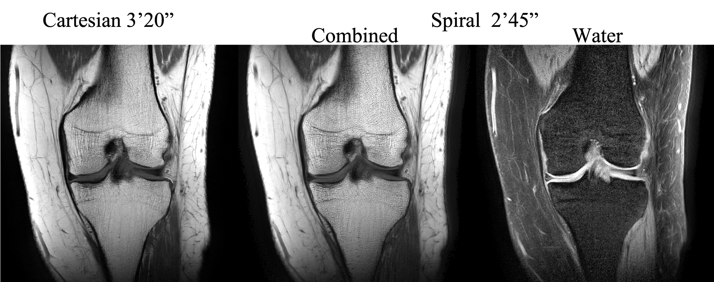
A 2D SE sequence with spiral out readout5 was employed to acquire T1W images. Unlike 2D spiral SE brain imaging5, flow is not a concern in coronal knee exams. Hence, through-plane crushers were removed and in-plane crushers were minimized to obtain a shorter TE of 8 ms. For similar reasons, the readout for Cartesian TSE T1W sequence was in HF direction unlike PDW and T2W sequences.
Radial Plane imaging
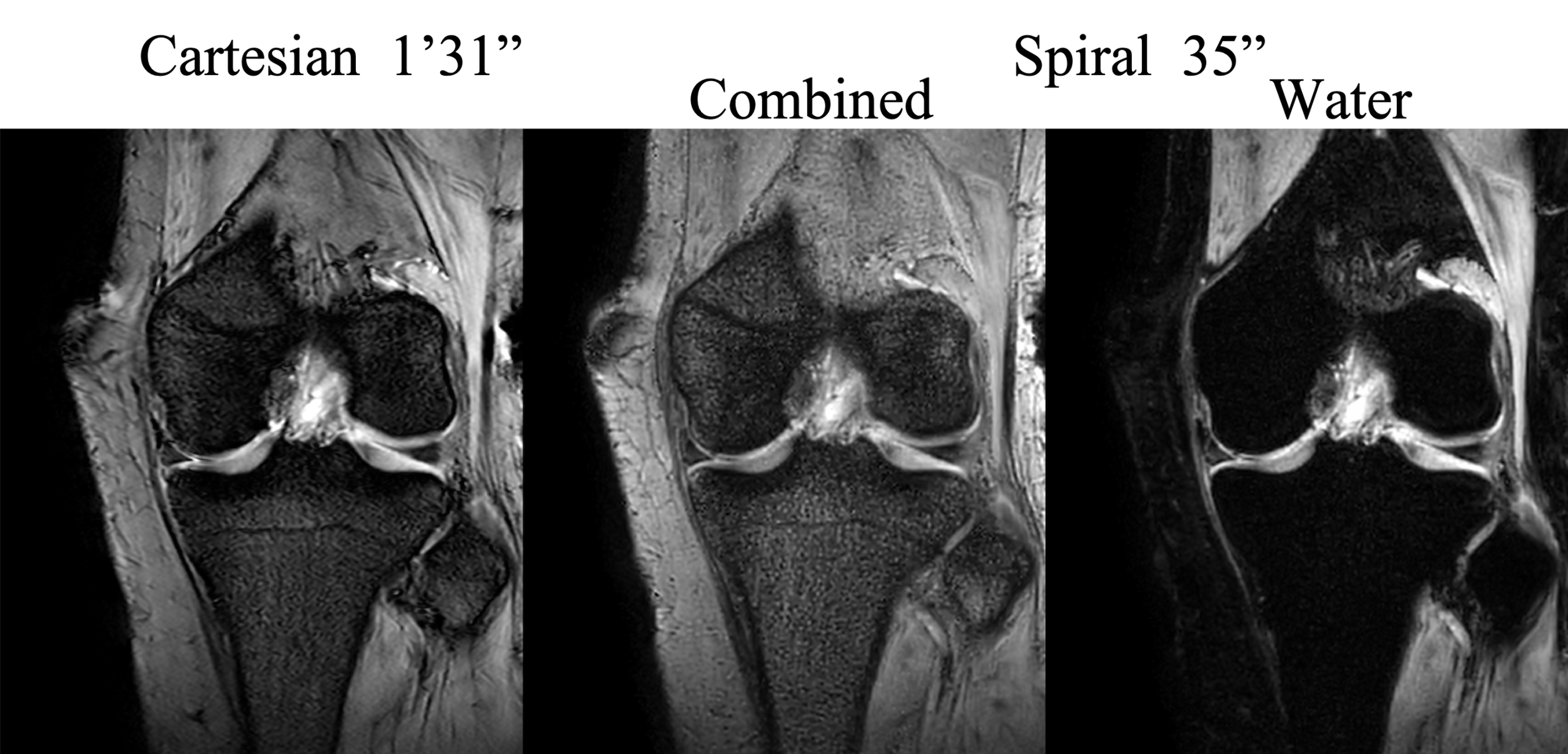
The medial and lateral menisci were imaged in separate scans. In each scan, cross-sectional images were obtained in 9 radial slices that are perpendicular to the meniscus in an interleaved mode3,4. A low flip angle of 15⁰ was used with a repetition time (TR) of 415 ms to mitigate the vertical low-signal band at the center of each image.
Results and Discussion
The spiral water-only and water-fat combined images are shown and compared with the Cartesian images in Figures 1-4. The overall contrast, SNR and sharpness of spiral PDW and T1W images are comparable to the Cartesian reference images. The spiral images have more textured appearance in bone marrow, which might be partially due to the increased T2* weighting in spiral readouts. The flow artefacts from the popliteal artery in the spiral Dual SE are mitigated, with only minor residues seen in T2W images (Figure 2). Cartesian T2W images have slightly higher SNR than spiral T2 images because, the Cartesian sequence has shorter TE and longer total readout time. It is straightforward to increase the number of spiral interleaves if higher SNR is preferred, at the cost of slightly longer scan-times. Alternatively, 2D spiral TSE10 with short echo train length (ETL) can be used to improve the SNR efficiency. Spiral images in radial plane demonstrate similar visibility of the menisci compared to the Cartesian scans (Figure 4), with only 38% of scan time.Conclusion
This work has demonstrated the feasibility of using spiral Dixon imaging for high resolution knee MRI exams.Acknowledgements
This work was funded by Philips Healthcare.References
1. American college of Radiology. ACR–SPR–SSR practice parameter for the performance and interpretation of magnetic resonance imaging (MRI) of the knee. Revised 2015 (Resolution 6).
2. Shapiro L, Harish, Hargreaves, Staroswiecki E, Gold G. Advances in musculoskeletal MRI: technical considerations. J Magn Reson Imaging. 2012;36(4):775-87.
3. Ehman RL, Berquist TH. Fast radial imaging of the knee. In proceedings of Science Meeting of Society of SMRM, Berkeley, USA. 1988. Abstract 415.
4. Quinn SF, Brown TR, Szumowski J. Menisci of the knee: radial MR imaging correlated with arthroscopy in 259 patients. Radiology. 1992;185(2):577-580.
5. Li Z, Hu HH, Miller JH, Karis JP, Cornejo P, Wang D, Pipe JG. A spiral spin-echo MR imaging technique for improved flow artifact suppression in T1-weighted postcontrast brain imaging: A comparison with cartesian turbo spin-echo. Am J Neuroradiol. 2016; 37 (4):642-7.
6. Wang D, Li Z, Pipe JG. 3D MP-RAGE with distributed spirals. In proceedings of the 23th Science Meeting of ISMRM, Toronto Canada, 2015. Abstract 3635.
7. Li Z, Wang D, Karis JP, Pipe JG. A dual spin-echo technique with hybrid spiral readouts for fast simultaneous proton density- and T2-weighted fat-water imaging, In proceedings of the 24th Science Meeting of ISMRM, Singapore, 2016. Abstract 1833.
8. Wang D, Zwart NR, Pipe JG. Joint water-fat separation and deblurring for spiral imaging. Magn Reson Med. 2018;79:3218-3228.
9. Del Grande F, Santini F, Herzka DA, et al. Fat-suppression techniques for 3T MR imaging of the musculoskeletal system. RadioGraphics 2014; 34:217-233.
10. Li Z, Karis JP, Pipe JG. A 2D spiral turbo‐spin‐echo technique. Magn Reson Med. 2019;80:1989-1996.
Figures