3704
TRASE Enforced and Accelerated Nonlinear Spatial Encoding for Low-field Portable MRI and its Local k-space Analysis1EPD, Singapore University of Technology, Singapore, Singapore, 2Chiba University, Chiba, Japan
Synopsis
We propose an encoding method which combines Transmit Array Spatial Encoding (TRASE) and spatial encoding magnetic field (SEM) to improve the image quality in a permanent-magnet-array (PMA)-based low-field portable MRI system with acceleration. TRASE is used to introduce phase shift to re-arrange the signal points in local k-spaces, to gain more information quicker to increase imaging quality and speed. A significant quality improvement can be achieved in the reconstructed images, especially in the central regions, which is shown numerically. The number of rotation angles is reduced 80% for the same image quality. The experiments are being conducted for a validation.
PURPOSE
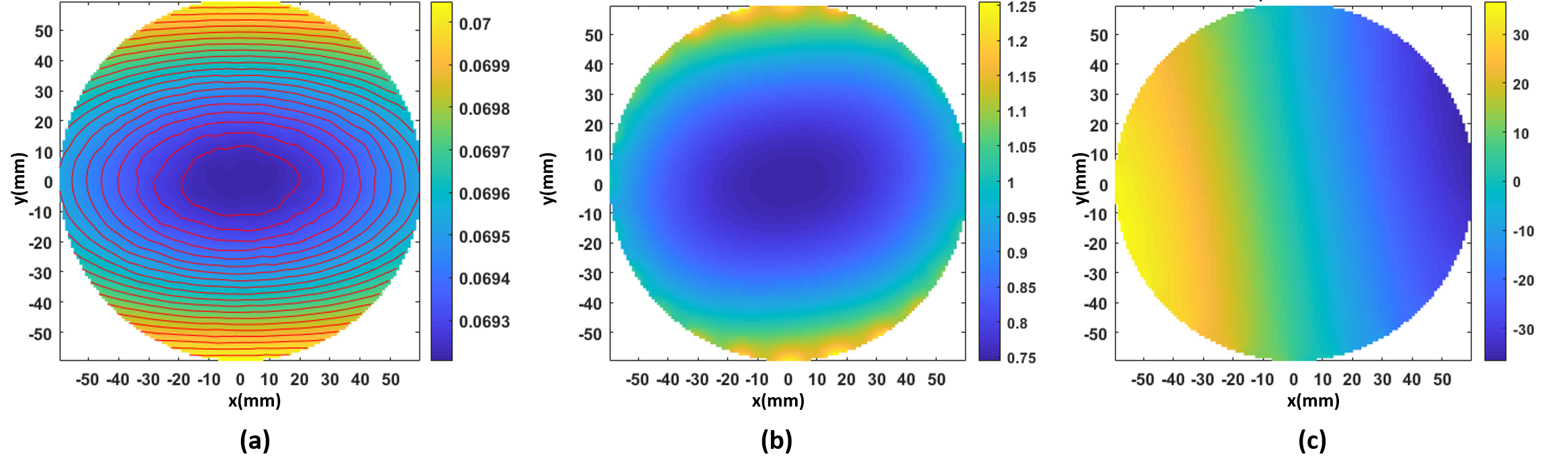
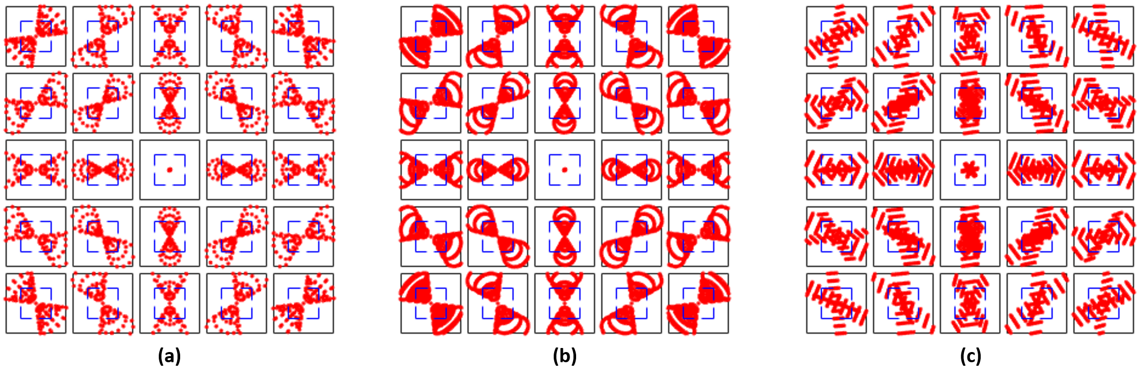
Using the magnetic field supplied by a permanent-magnet-array (PMA) as a spatial encoding field (SEM) circumvent the need for heavy and power-hungry gradient coils in an MRI system, leading to simplified hardware and a possibility towards a portable MRI. However, this kind of SEMs usually has non-linear gradients and irregular patterns (e.g. the measured field pattern in Fig.1(a) of a short Halbach array [1]). Due to the non-uniform gradient distribution in the SEM, the distributions of signal points in local k-spaces that correspond to the sub-field-of-views(FoVs) are not identical nor all well spread out (as shown in Fig.2(a))[2] where the confined ones result in low image quality. This limits the global image quality (e.g. column-1 and 2 in Fig.3) and thus the application of such an MRI system. We propose the application of Transmit Array Spatial Encoding(TRASE) coil to spread out the signal points in local k-spaces so as to improve image quality without extra hardware or cooling system. It effectively reduces the required number of rotation angles (Nq) for the same image quality, making system less sensitive to rotation errors. The proposed approach can be used to guide the design of a more sophisticated TRASE coil to compensate the non-linearity of SEMs in other PMA-based portable MRI systems.METHOD
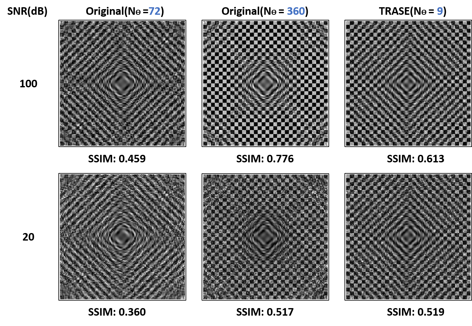
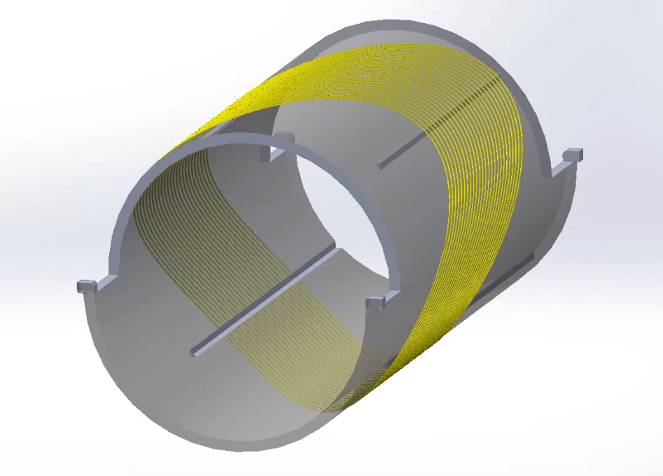
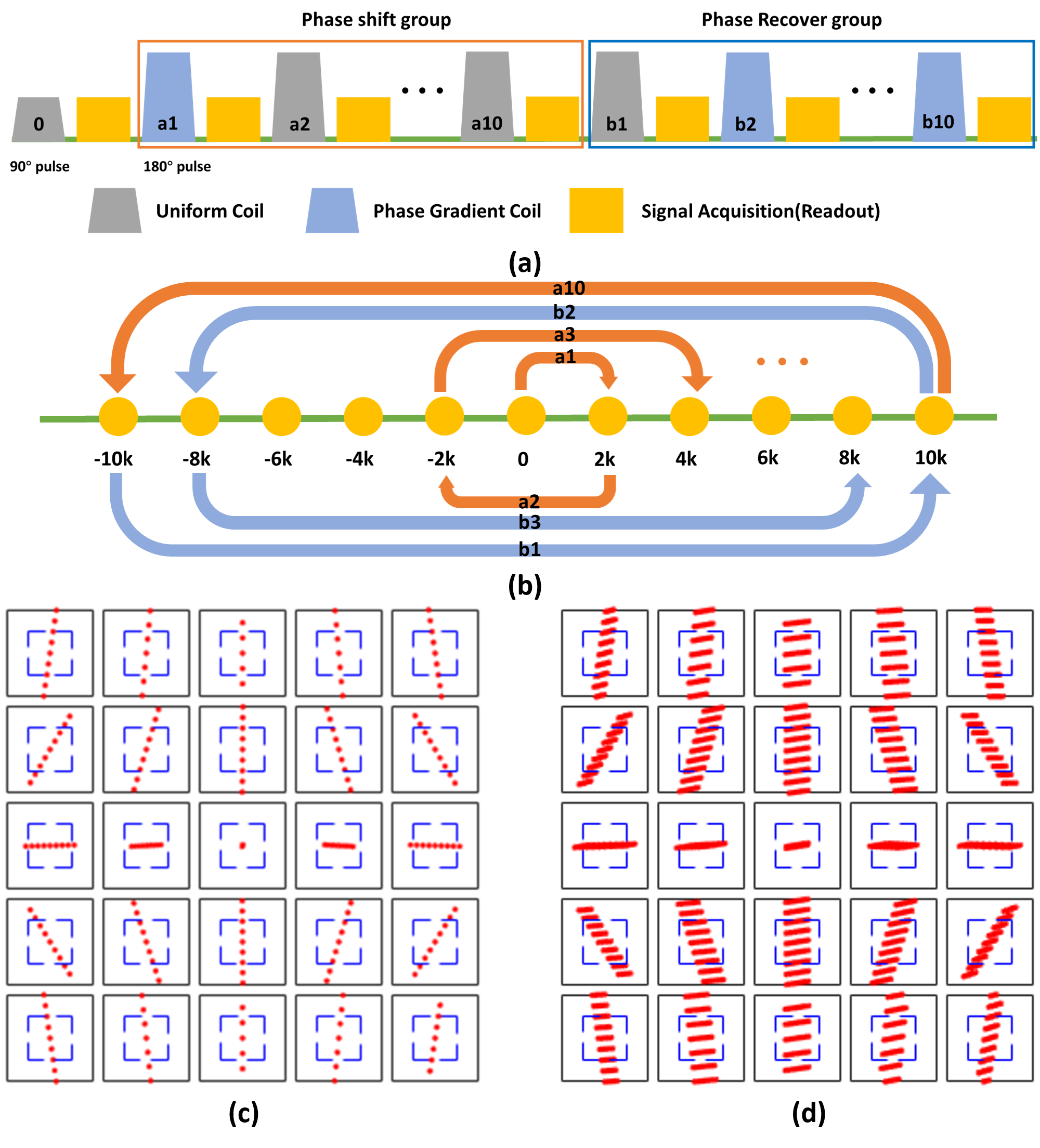
Fig.4 shows the design of the TRASE coil for an MRI system with a short Halbach array (with an inner diameter of 160mm)[1] whose magnetic field distribution is shown in Fig.1(a). It consists of a saddle coil that generates homogenous B1 and a variant coil that generates a linear B1 phase gradient along the x-direction[2]. Fig.1(b) and (c) show the magnitudes and phase of the TRASE coil. Because a constant gradient of the SEM is not required in a non-linear system, this allows a large phase gradient which is obtained by twisting the solenoid as shown in Fig.1(c).A MATLAB code based on Biot-Savart law was written to fast calculate the field distribution based on the configuration of the traces of the coil. The FoV was set to 120mx120mm located at the center of the magnet array. Fig.5(a) shows the TRASE pulse sequence designed to generate three types of signals with different phase shifts in each coil in one echo train, and Fig.5(b) shows the corresponding trajectory of a k-vector in the k-space. Fig.5(c) and (d) shows the local k-space of a single rotation angle before and after applying the TRASE sequence. As shown in Fig.5, the pulse sequence effectively spread out the signal points in k-space. Reconstructed images were generated numerically for the MRI system without and with the proposed TRASE coil. The FoV was sampled as 128x128 pixels. A chessboard with a grid size of 3.75mm was used as the phantom. To evaluate the limitation of improvement by the introduction of the proposed TRASE coil, noise levels of 100dB (an average level for a high-field system) and 20dB (an average level for a low-field system) were added to the system. The original system with Nθ=72 was simulated as a reference. For a comparison, Nθ in the original system was increased to 360 to gain the same number of encoding equations as that of the system with the TRASE coil.
RESULTS
Column-1, 2, and 3 in Fig.3 shows the reconstructed images for the original system with Nq=72 and 360 and that of the system with the proposed TRASE coil when Nθ=9. Row-1 and 2 correspond to the cases at a noise level of 100dB and 20dB, respectively. As shown in Fig.3, the central area is always distorted and blurry in the original system even though the number of angles increases from 72 to 360. When the TRASE coil is applied, the central area becomes clear and the image quality of each sub-FoV tends to be more uniform. When SNR decreases to 20dB (row-2 in Fig.3), the distortion in the central region in the original system is more serious but the system with TRASE still can provide a relative clear pattern in the same region.DISCUSSION
The effectiveness of TRASE on improving the image quality of a PMA-based MRI system can be analyzed using local k-spaces. Fig.2(c) shows the local k-spaces of the system with TRASE. As shown, the introduction of TRASE helps to rearrange the position of signal points (i.e. k-vectors) to cover more area, which leads to improve the reconstructed image. This effect is clearly seen in the all the sub-FoVs where it is observed that the areas covered by the signal points have been significantly enlarged, especially the central one. Compared to the case by increasing Nθ to 360, the coverage area is significantly improved in the central sub-FoV, and comparable to in the rest of the FoV. This leads to the improvement of image quality, especially in the central region. Increasing the phase gradient helps to increase the coverage in the local k-spaces, thus further improving image quality. However, it makes the magnitude of B1-field less homogeneous. With an increased inhomogeneity, when the TRASE pulse is long, the off-resonance effect is significant, which in turn compromises SNR and generates aliasing in the reconstructed image.Acknowledgements
No acknowledgement found.References
[1] Ren, Zhi Hua, et al. "Magnet array for a portable magnetic resonance imaging system." 2015 IEEE MTT-S 2015 International Microwave Workshop Series on RF and Wireless Technologies for Biomedical and Healthcare Applications (IMWS-BIO). IEEE, 2015.
[2] Gong, Jia, et al. "Effects of Encoding Fields of Permanent Magnet Arrays on Image Quality in Low-Field Portable MRI Systems." IEEE Access 7 (2019): 80310-80327.
[3] Sun, Hongwei, Stephanie Yong, and Jonathan C. Sharp. "The twisted solenoid RF phase gradient transmit coil for TRASE imaging." Journal of Magnetic Resonance 299 (2019): 135-150.
Figures