3702
3D Inner Volume MR Fingerprinting with Parallel Transmission1Center for Magnetic Resonance Research, University of Minnesota, Minneapolis, MN, United States
Synopsis
In this simulation study, we explored the feasibility of incorporating parallel transmission to achieve a 3D inner volume MR fingerprinting with an aim to mitigate field inhomogeneities at UHF and reduce field of view (rFOV) for high resolution acquisitions and improved parameter estimation. Our preliminary results showed uniform and consistent contrast within the rFOV. We are currently working on the implementation of the method for further experimental validations.
Introduction
Magnetic resonance fingerprinting (MRF) (1) has been introduced as a rapid and quantitative MR imaging technique with many potential clinical and research applications. While most studies focus on standard clinical field strengths, the SNR advantages at ultra-high field (UHF) promise to benefit MRF by supporting higher spatial resolutions. However, to mitigate the B1+ inhomogeneity at UHF more complicated dictionary modeling is typically required which includes the modeling of spatial varying transmit B1+ fields (2-4). For body imaging such as prostate, a longer scan is also required due to the need to encode the entire plane of excitation which limits acquisition efficiency. In this study, we explore the possibility of using tailored 3D selective parallel transmission (pTx) excitation pulses to address transmit B1+ issues as well as enable reduced field of view (rFOV) imaging which can reduce scan time with the promise of improved parameter estimation at UHF. The feasibility of the proposed methods is demonstrated through a simulation study, with ongoing efforts to implement the methods to experimentally validate.Methods
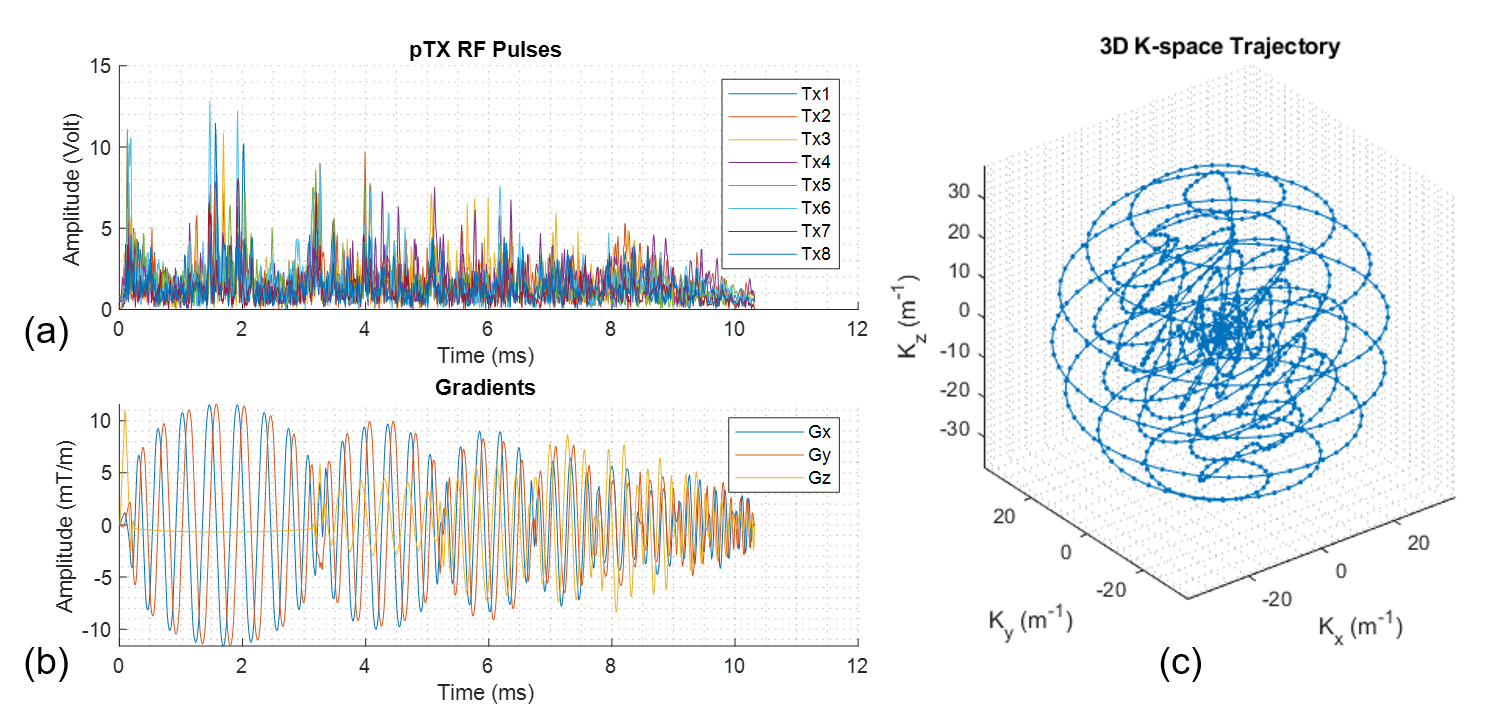
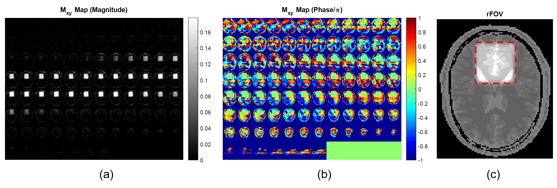
- 3D RF Pulse DesignA 3D spherical spiral-in multi-shell k-space trajectory (5-7) was designed to provide a 3D excitation pulse with a nominal field of excitation (FOX) of 60 mm and a maximum gradient slew rate of 162 T/m/s resulting in a 10.32 ms pulse. A flat B0 map and simulated B1+ maps at 7T from an 8-channel transmit loop head coil was used for the pulse design following the spatial domain method (8). The RF pulses, gradients and k-space trajectory are shown in Figure 1, with the simulated excitation profile of the pulse shown in Figure 2.
- MRF Sequence Design
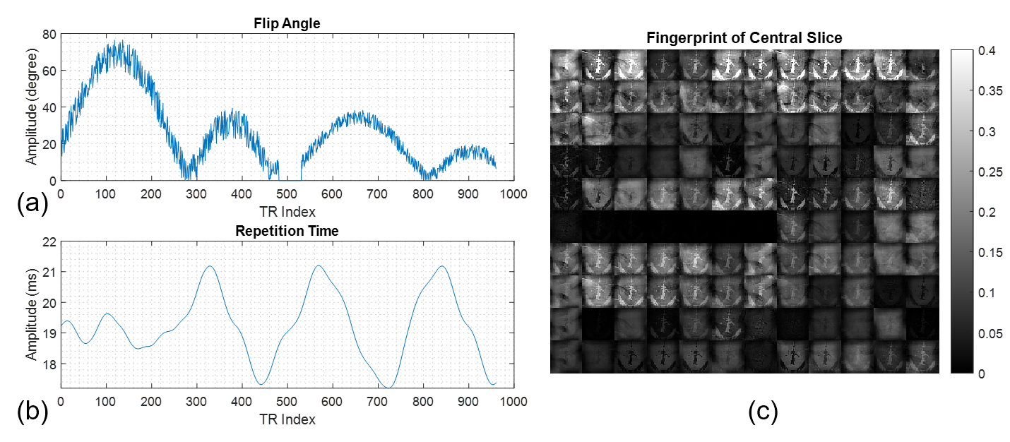
We implemented the original TrueFISP based MR fingerprinting design (1) in the simulation. As proof of principle, 960 time points were used to simulate the spin evolution. The flip angle and repetition time (TR) evolution are shown in Figure 3. Due to the length of the 3D pulse, the resulting TR increased ranging from 17.2 to 21.2 ms versus 10.5 to 14 ms in the original MRF paper (1). However, when acquiring with an rFOV, the read-out duration can remain the same for a higher resolution or reduced when maintaining the same resolution.
- Simulation Method
A 2mm isotropic numerical brain phantom (9) with a field of view of 217x181x181mm3 was used in simulation. Rather than imaging the nominal FOX of 60 mm, a slightly larger rFOV of 72 mm was spatially encoded considering the transition band of the designed RF pulses. Relaxation during RF excitation was simulated to account for the non-analytical nature of the tailored RF pulses. Instead of using a specific 3D read-out trajectory, we simplified the simulation by fully sampling the zoomed FOV with a different orientation each time frame, allowing the outer volume signal resulting from the imperfections of the RF pulses to be aliased into the FOX in a less coherent manner. The read-out acquisition matrix was 36x36x36 with 2mm isotropic resolution and images were reconstructed using NUFFT (10). Dictionary matching was done using a conventional dot-product approach (1).
Results
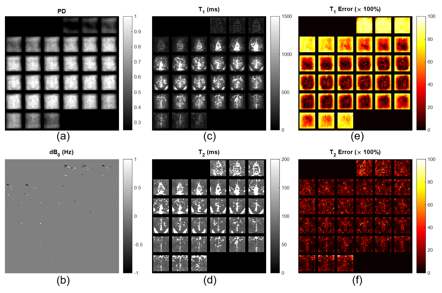
The reconstructed parametric maps including proton density, off-resonance, T1 and T2 are shown in Figure 4.a – 4.d, respectively. The quantification error maps of T1 and T2 are shown in Figure 4.e and 4.f. In general, the maps show good and consistent contrast in gray matter, white matter and CSF without aliasing artifacts. The uniformity within these tissues also suggest effective mitigation of B1+ inhomogeneities. Quantification deviations were mainly observed at the edge of the imaged rFOV, namely the transition band of the pulse where the excitation profile degraded. Additionally, residual errors in parameter estimation most likely come from the limited length of fingerprints and discretization errors, both of which should resolve in actual measurements.Discussion
Our preliminary simulation results demonstrated the potential of using pTx to achieve a reduced FOV for MR fingerprinting. While parallel transmission has been primarily used to mitigate B0 and B1+ inhomogeneity at UHF, it may also help reduce data acquisition and dictionary size for MRF and thus improve the robustness of parameter estimation. With a reduced FOV, additional acceleration factor or improved spatial resolution may possibly be achieved. Despite the imperfections of the tailored pulses, the pseudo-randomized acquisition and pattern matching reconstruction as used by MRF may effectively mitigate such imperfections and therefore find useful application at UHF especially for body imaging. However, additional strategies are needed to tackle with lipid in the skull and torso, especially when considering that the receive sensitivity profile may further enhance the contamination by the outer volume signal, requiring more pulse optimization strategies to improve the excitation fidelity and overall performance.Conclusion
We have demonstrated the potential of 3D inner volume MR fingerprinting with parallel transmission. The proposed method is currently being implemented for experimental validations in the brain and body.Acknowledgements
Apart from grant support from NIBIB P41 EB027061, the authors would like to thank Seng-Wei Chieh for constructive discussion.References
1. Ma D, Gulani V, Seiberlich N, Liu K, Sunshine JL, Duerk JL, Griswold MA. Magnetic resonance fingerprinting. Nature 2013;495(7440):187-192.
2. Buonincontri G, Schulte RF, Cosottini M, Tosetti M. Spiral MR fingerprinting at 7 T with simultaneous B1 estimation. Magnetic Resonance Imaging 2017;41:1-6.
3. Buonincontri G, Sawiak SJ. MR Fingerprinting with Simultaneous B1 Estimation. Magnet Reson Med 2016;76(4):1127-1135.
4. Cloos MA, Knoll F, Zhao T, Block KT, Bruno M, Wiggins GC, Sodickson DK. Multiparametric imaging with heterogeneous radiofrequency fields. Nat Commun 2016;7:12445.
5. Wong ST, Roos MS. A strategy for sampling on a sphere applied to 3D selective RF pulse design. Magn Reson Med 1994;32(6):778-784.
6. Malik SJ, Hajnal JV. Phase relaxed localized excitation pulses for inner volume fast spin echo imaging. Magn Reson Med 2016;76(3):848-861.
7. Lustig M, Kim SJ, Pauly JM. A fast method for designing time-optimal gradient waveforms for arbitrary k-space trajectories. IEEE Trans Med Imaging 2008;27(6):866-873.
8. Grissom W, Yip CY, Zhang Z, Stenger VA, Fessler JA, Noll DC. Spatial domain method for the design of RF pulses in multicoil parallel excitation. Magn Reson Med 2006;56(3):620-629.
9. Collins DL, Zijdenbos AP, Kollokian V, Sled JG, Kabani NJ, Holmes CJ, Evans AC. Design and construction of a realistic digital brain phantom. Ieee T Med Imaging 1998;17(3):463-468.
10. Fessler JA, Sutton BP. Nonuniform fast Fourier transforms using min-max interpolation. Ieee T Signal Proces 2003;51(2):560-574.
Figures