3701
Sub-µs gradient delay correction in tilted slab-selective bipolar multi-spoke RF pulses using trim blips
Redouane Jamil1, Vincent Gras1, Franck Mauconduit1, and Nicolas Boulant1
1CEA, Université Paris-Saclay, NeuroSpin, Gif sur Yvette, France
1CEA, Université Paris-Saclay, NeuroSpin, Gif sur Yvette, France
Synopsis
Bipolar spokes RF pulses can be employed in parallel transmission (pTX) used to mitigate the RF field inhomogeneity problem at ultra-high field in 2D. However, their performance can dramatically drop with delays between gradients and RF pulses. This work reports a new method for (anisotropic) gradient delay correction for multi-spoke RF pulses based on so-called gradient trim blips, applicable to tilted slice and slab excitations. This solution has been tested in Bloch simulation and validated on phantom at 7T with tilted slab-selective pulses. Experimental results obtained with the corrected pulses match the simulations incorporating no gradient delay.
Purpose
Parallel transmission (pTX) versatility is exploited in multi-spoke1 RF pulses to tackle the RF inhomogeneity problem at ultra-high field. Due to its robustness versus gradient delays, monopolar pulses are easier to use but are less robust versus ΔB0 and can impact the minimum TR in fast acquisitions. For those reasons, bipolar spokes are preferred but their sensitivity to gradient delays can quickly deteriorate performance. The most direct way to correct for those delays is to shift temporally the RF waveform2 but this requires a high discretization of the RF shapes to account for µs delays, increasing loading time, and it is not applicable to anisotropic delays when dealing with tilted slices or slabs. Gradient delays can also be corrected by adding a phase shift to every other spoke for slice excitations3 where the slice location center is relatively well-defined in space. As a result, it is neither applicable for slab excitations and nor for anisotropic delays. The new method reported, gradient trim4 blips, here consists in adding gradient blips between RF sub-pulses to cancel the phase shift induced by the gradient delays. We demonstrate its applicability for tilted slab-selective pulses on a water phantom at 7T.Methods
Experiments were carried out on a 7T Siemens (Siemens Healthcare, Erlangen, Germany) Magnetom system equipped with an SC72 gradient (40 mT/m nominal maximum gradient strength and 200 T/m/s max slew rate) and the Nova (Nova Medical, Wilmington, USA) 8Tx-32Rx pTX coil. Gradient delays were first characterized based on the method detailed in Gras el al.3 where a slice location dependent phase shift characterizes the gradient delay. The effect of a gradient delay on RF phase for a z location is shown in Fig.1. The first gradient slope, the refocusing lobe and the last gradient slope do not affect the flip angle. Gradient plateaus where RF pulses are applied are displayed. On the first gradient lobe, the part of the plateau lasting Tp - Δt generates a rotation along z axis whose angle is proportional to the same duration, the second part during the RF pulse generates a rotation R1 , the third part of the plateau generates a rotation along $$$\overrightarrow{z}$$$ whose angle is proportional to Tp + Δt. The first and last parts of the second plateau also produce the same rotations but around $$$-\overrightarrow{z}$$$. Gradient commutations (i.e. the middle gradient slopes) induce a zero-order eddy current that can be modelled as a z-rotation. The total rotation matrix is then:$$R_{TOT}=R_{-\overrightarrow{z},T_{p}-\triangle t}R2R_{\overrightarrow{z},\phi_{EC}}R_{\overrightarrow{z},2\triangle t}R1R_{\overrightarrow{z},T_{p}-\triangle t}$$
We can see here that gradient delays induce a phase shift on the spins between the two RF pulses, yielding 30° phase shift per µs and for 20 mT/m gradient at 5 cm from the isocenter. The zero-order eddy current rotation can be corrected by a uniform phase shift of the second RF sub-pulse while the spatially dependent rotation with angle 2γGsszΔt (Gss is the slice selection gradient amplitude, z the center of the slab) can be compensated for all positions by a gradient blip. For the case of tilted slabs/slices and anisotropic delays, this correction is simply applied separately for each axis employed in the slice or slab selection. Pulse design and acquisitions were performed with 2 spokes bipolar pulses on a gel phantom. An AFI5 sequence was used to measure the flip angle for two configurations: axial and tilted orientations (4cm slab thickness). A TBWP of 25 (sub-pulse duration 1.9 ms, gradient strength 7.7 mT/m) and an additional delay up to 16µs were used to enhance gradient delay artefacts. Delays were modelled in simulation by simply shifting the waveform of the gradients. Experimental results were compared to simulations and unipolar acquisitions as a reference since unipolar pulses are immune to gradient delays.
Results
Delays of 3.5 µs on x and 4 µs on y and z were measured. Figure 2 shows flip angle maps of bipolar acquisitions compared with simulations; where a good similarity between the experimental results and the theoretical predictions can be observed. Figure 3 for reference shows the ratio of the bipolar (with and without trim blips) results to the unipolar RF pulse version, a ratio of 1 indicating perfect correction of the gradient delays, provided the ΔB0 effect can be neglected.Discussion and conclusion
We have presented a method to correct for gradient delays in pTX bipolar spokes. Since the correction relies on additional gradient (trim) blips, the accuracy of the compensation method depends proportionally on the fidelity of their areas, thereby leading to sub-µs accuracy given standard scanners. It is a general solution as it is applicable for both slice and slab excitations as well as anisotropic gradient delays.Acknowledgements
ERPT equipment program of the Leducq Foundation.References
[1] Saekho and al. MRM 2006 Apr;55(4):719-24., [2] Tse and al. MRM 2017 Nov;78(5):1883-1890., [3] Gras and al. MRM. 2017 Dec;78(6):2194-2202. [4] Oelhafenand al. MRM. 2004 Nov;52(5):1136-45. [5] Yarnykh MRM 2007 57:192–200Figures
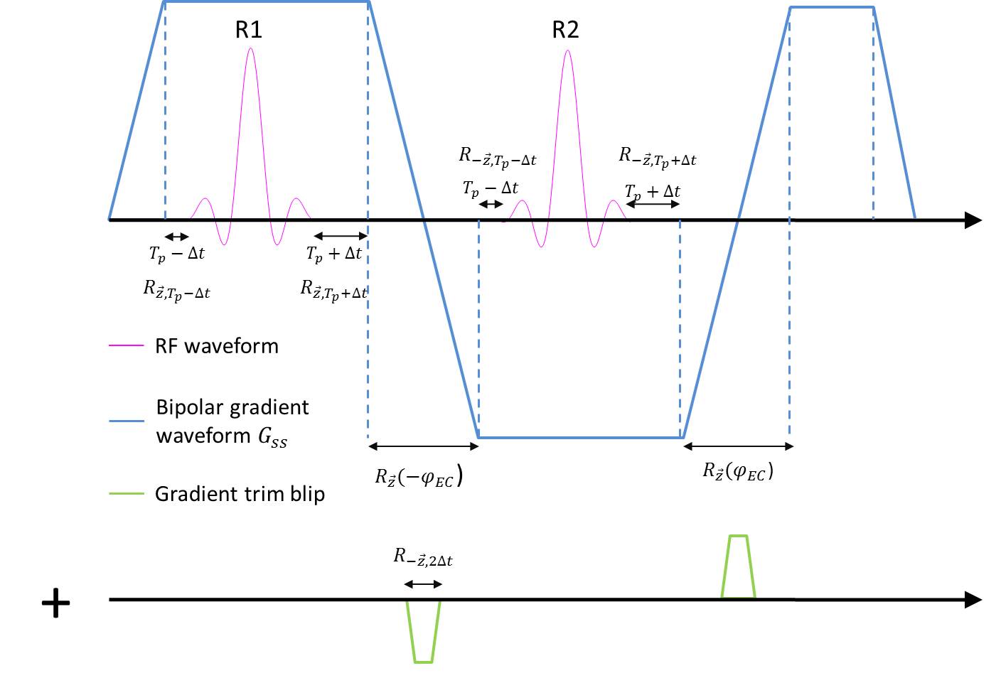
Figure 1. Bipolar RF pulse used in the
simulations and acquisitions. For demonstration purposes, the RF sub-pulses are
padded with zeros for a duration Tp. With gradient delays, rotations during
these periods are modified affecting the phase of the second sub-pulse. By appending
to the first slice selection gradient Gss (blue)
a well-chosen gradient trim blip (green), the phase-shift of the second sub-pulse
can be cancelled. The second gradient blip is for intra-voxel refocusing.
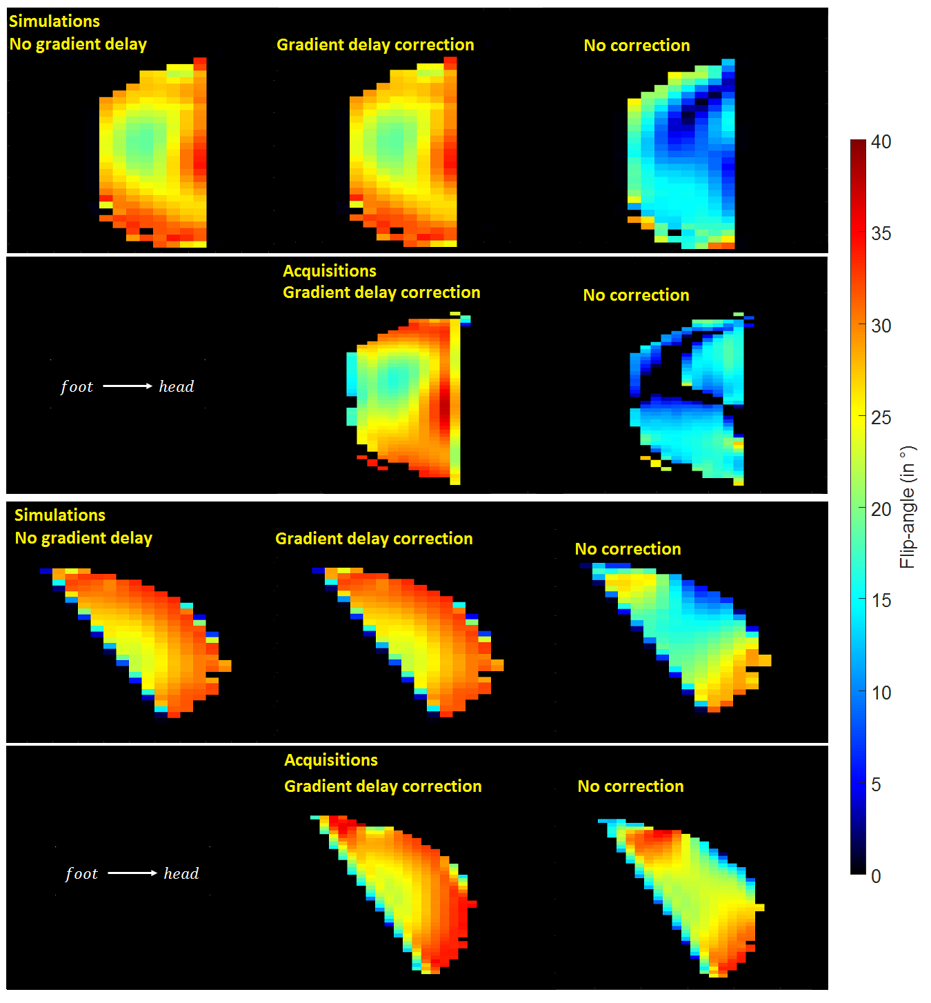
Figure 2. Flip Angle maps (°) returned
by Bloch simulations and acquisitions with a slab-selective 2 spoke bipolar RF pulse
(target flip angle 30°). Both slabs are 4 cm thick and shifted by 4.5 cm from
isocenter. The second slab is tilted by 20° about LR axis. For each slab, on
top, computed simulations with and without correction are displayed, bottom
row, 7T acquisitions. In simulation, trim blips correct perfectly for the
gradient delays (top, first two columns) while there is good agreement between
simulations and experiments for both corrected and uncorrected scenarios.
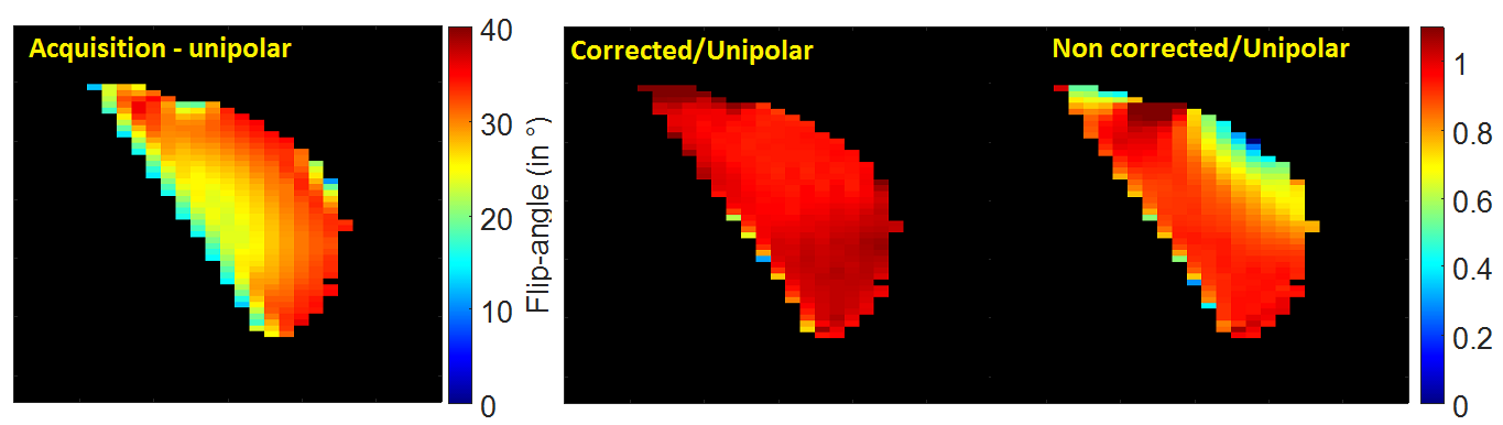
Figure 3. Comparison between measured bipolar
and unipolar flip angle maps. On the left, the flip-angle map (in °) of the unipolar
acquisition is displayed. The same RF coefficients and slab position were used
for the bipolar case. On the right, the ratio between the acquired bipolar maps
and the unipolar are shown.