3700
Large tip-angle, motion robust pulse design for parallel transmission at 7T using composite B1 distributions.1CUBRIC, School of Psychology, Cardiff University, Cardiff, United Kingdom
Synopsis
Parallel-transmit (pTx) pulses can help overcome B1 inhomogeneity at ultra-high field, however their performance is sensitive to geometry, orientation and composition of the coil load. Head motion in pTx effectively alters the load, damaging pulse performance and reintroducing artificial contrast to images. Here, we introduce a versatile method to reduce in-plane motion sensitivity of large tip-angle, parallel transmit pulses by designing pulses based on weighted-average B1-distributions. These include B1-distributions from multiple head positions to effectively expand the area over which the pulse can function. Error in resulting inversion profiles is reliably reduced following most in-plane translations and rotations, demonstrating motion-robustness.
Introduction
Parallel transmit (pTx) arrays with tailored pulses (designed using the load-dependent B1-distribution) can help overcome characteristic B1-inhomogeneity at ultra-high field (UHF; ≥7 Tesla) MRI to produce uniform flip-angle throughout the imaged volume1-4. B1-mapping is usually conducted once and resulting pulses are used throughout the scan, effectively tailoring the pulse to the subject and their head position during the mapping.It was previously shown that head motion commonly causes flip-angle error (normalised root mean-squared error; nRMSE) of 20-30% and up to 90% for large movements in the small tip-angle (STA) regime5. Our initial investigations indicate that the iterative nature of most large tip-angle (LTA) design methods augments motion-induced error and makes it less spatially uniform (data not shown).
Here, we generate composite B1-maps that cover a larger area than the head by weighted-averaging B1-maps that belong to multiple head positions. These averaged B1-maps are used to design LTA inversion pulses, which achieve an inversion profile in a larger area across the field of view, introducing motion robustness. Direction-specific pulses are designed offline, forming a library from which the pulse to play at any timepoint can be determined by head position.
Methods
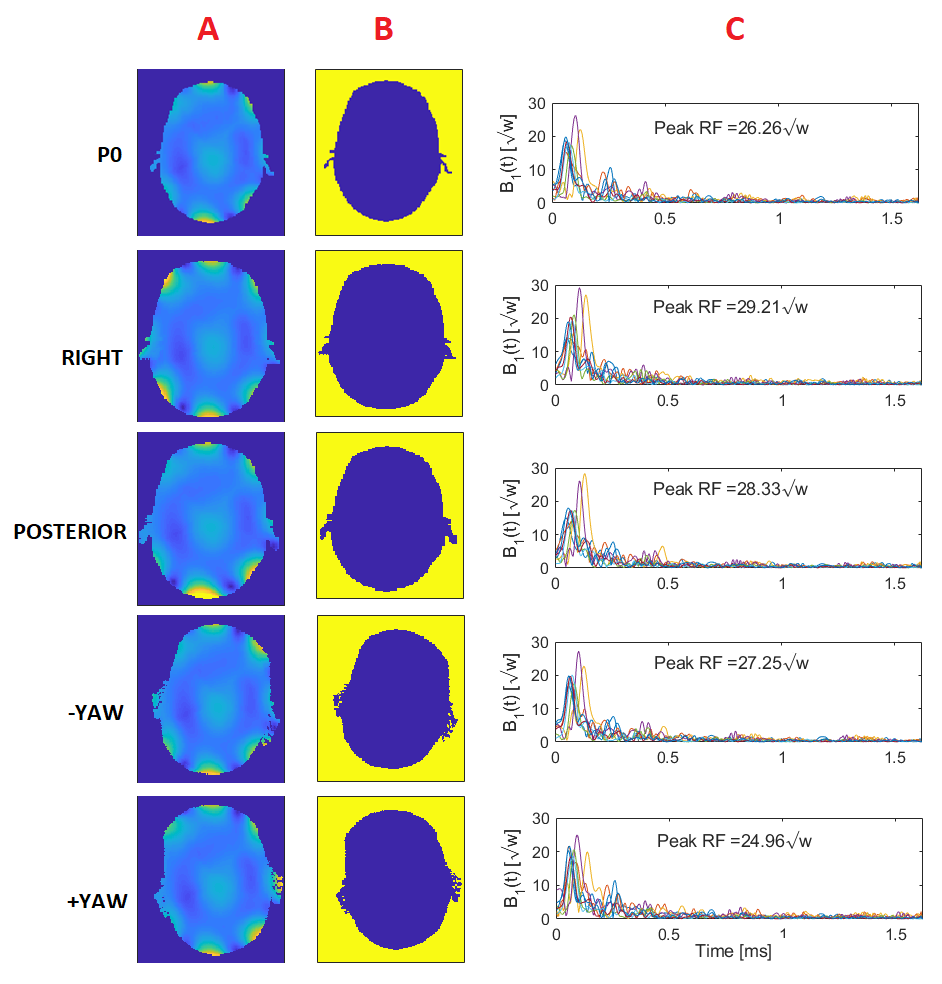
B1-maps were generated using Sim4Life (ZMT, Zurich, Switzerland) with an 8-channel loop array tuned to 300MHz and the Ella body model (IT’IS, Zurich, Switzerland)6. In-slice head motion (1/2/5/10/15/20mm towards right, and/or 1/2/5/10mm towards posterior; or ±1/±2/±5/±10/±15/±20o rotation) was simulated by displacing the body model with respect to the array5.180o spiral trajectory inversion pulses were designed using a fast optimal control algorithm7 with either the central (i.e. unmoved) head position (P0) B1-distribution alone (conventional method), or the averaged, direction-specific B1-distribution (proposed method [Fig.1a]). Averaged distributions were defined as: $$ B1_{avg}(c,r) = \frac{\sum_{i=1}^{Np(r)}B1(i,c,r)w_i}{\sum_{i=1}^{Np(r)}w_i} $$ where Np(r) is the number of simulated positions in a given direction with non-zero B1-values in pixel r (e.g. Np(r) ≤7 ‘rightward’ positions along -X), B1(c,r) is the c’th channel’s complex B1-sensitivity at pixel r, and wi is a position-specific weighting factor used to prioritise performance with small movement over large, accounting for the higher likelihood of small movements by cooperative subjects. This resulted in 4 off-central (right, posterior, +yaw, -yaw) pulses (Fig.1c). For yaw, pulses were also designed for 5 additional axial slices (separated by 20mm) since motion susceptibility of pTx pulses has previously been reported to be slice-dependent5. Inversion profiles were evaluated using Bloch simulations for each pulse at all positions. nRMSE of the resulting profile was calculated with respect to target profile (Fig.1b).
Results
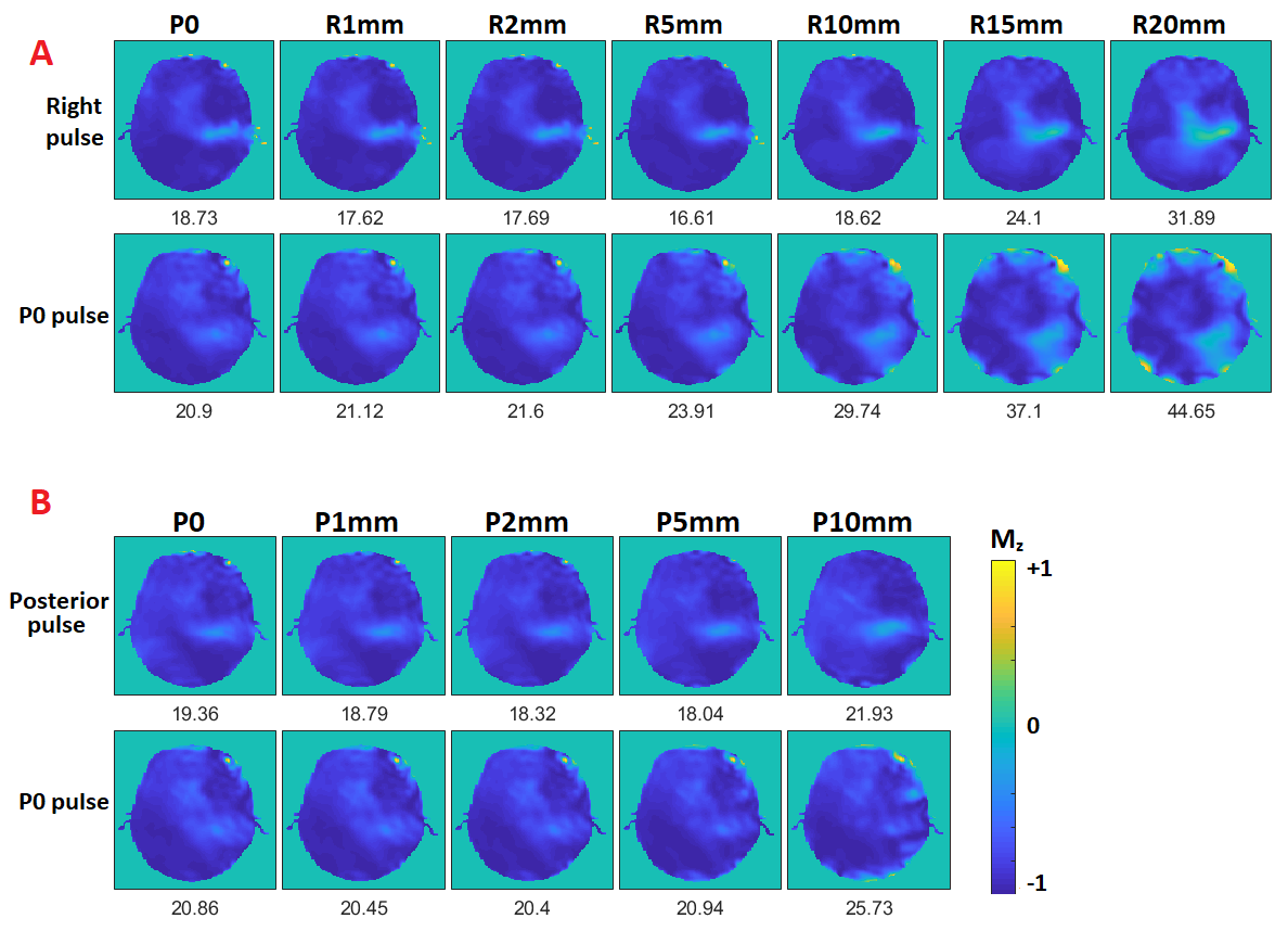
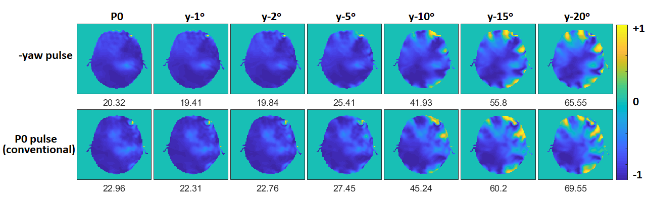
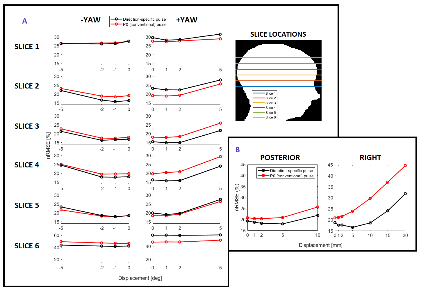
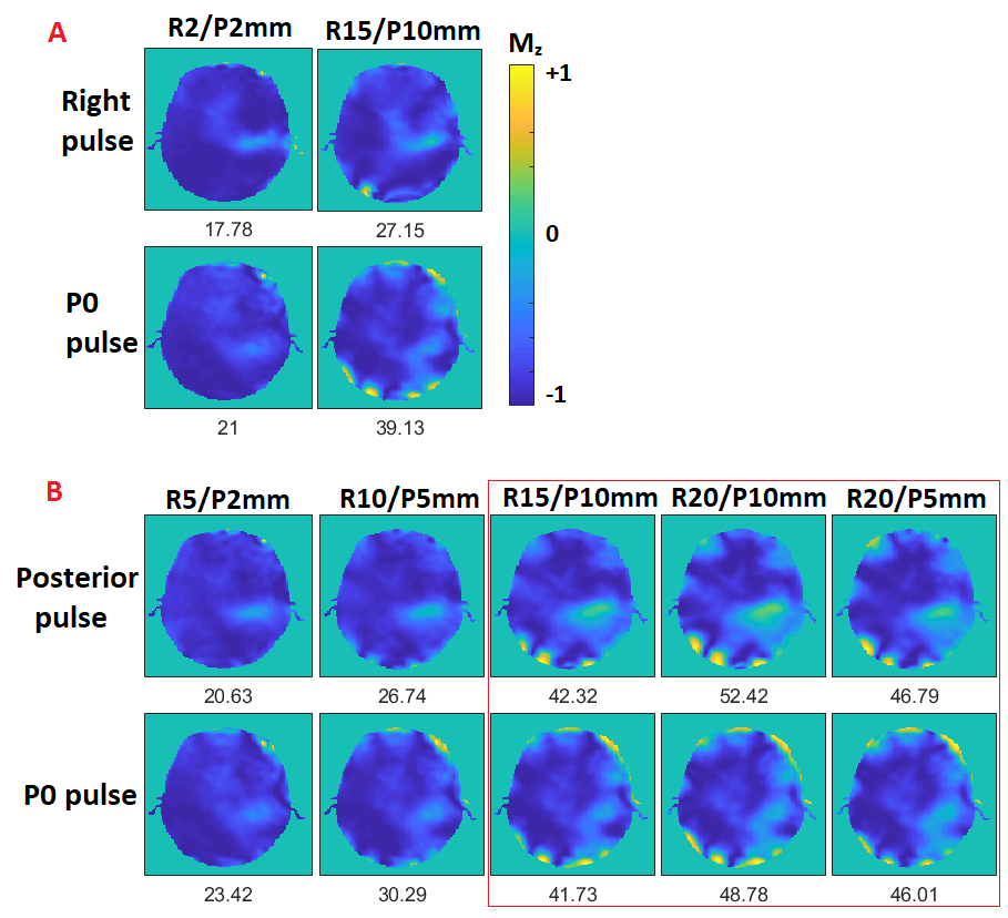
In all translation cases, inversion profile was improved using the proposed approach (Fig.2). nRMSE was reduced compared to the conventional (P0) pulse by an average of 7.7% (max = 13%) for rightward (Figs.2a & 4b), and 2.4% (max = 3.8%) for posterior movements, respectively (Figs.2b & 4b). Benefits were also seen for off-axis positions (which were not included in the B1-averaging) for 92% of cases by using the rightward pulse, or 83% of cases using the posterior pulse. Representative small and large off-axis movements are shown in Fig.5. The posterior pulse did not improve performance when the off-axis position included a large rightward component (red box in Fig.5).For -yaw, 79% of cases were improved using the proposed method. Qualitatively, the inversion profile remained smoother under yaw conditions when the direction-specific pulse was used (Fig.3). For +yaw, 38% of cases were improved. Though the inversion profile was reliably improved in slices 3&4, for peripheral slice locations (slices 1,2,5,6), the +yaw pulse did not improve performance (Fig.4a). Yaw ≥ 10o cases were omitted from Fig.4 for clarity since, although error was reduced relative to the conventional pulse, it remained at 40-60%.
Discussion
In-vivo implementation requires real-time positional information; possible with simple, low-resolution motion-tracking. When in-plane motion occurs, the appropriate direction-specific pulse is played out. Universal Pulses8 and SmartPulse9 are library-based approaches to reduce inter-subject anatomical variability effects on pulse performance while avoiding lengthy online pulse design. The method proposed here is versatile and conceptually compatible with both approaches, introducing motion-robustness to the library of pulses.The direction of the B1-field curve (counter-clockwise; the same as +yaw) may explain the lower improvement rate for +yaw, and is subject of ongoing investigations. Though error for yaw ≥ 10o was not reduced to acceptable levels, this is likely due in part to the weighting values assigned during the B1-averaging (performance for small shifts was prioritised). If large movement is expected (e.g. paediatric subjects), a pulse designed using weights which prioritise extreme positions can additionally be used.
Motion-induced local-SAR increases of 50-100% are not uncommon in the STA regime5. Fig.1c waveforms show that peak power in pulses designed using the proposed method is comparable to that of the conventional pulse, so global-SAR management based on RF power should not be significantly affected. Local-SAR behaviour of the developed pulses is subject of current work.
Conclusion
We have introduced a versatile method to reduce in-plane motion sensitivity of LTA pTx pulses by using composite B1-distributions. These include multiple head positions to effectively expand the area over which the pulse can function, resulting in superior inversion profiles following motion. The method helps overcome one of the remaining obstacles for pTx to be used widely.Acknowledgements
No acknowledgement found.References
[1] Katscher, U. and Bornert, P. (2006). Parallel RF transmission in MRI. NMR in Biomedicine, 19(3), 393-400.
[2] Katcher, U,. Bornert, P., Leussler, C., van den Brink, J.S. (2003). Transmit SENSE. Magnetic Resonance in Medicine,49(1), 144-150.
[3] Vaughan, J.T., Garwood, M., Collins, C.M., Liu, W., DelaBarre, L., Adriany, G., Andersen, P., Merkle, H., Goebel, R., Smith, M.B. and Ugurbil, K. (2001). 7T vs. 4T: RF Power, Homogeneity and Signal-to-Noise Comparison in Head Images. Magnetic Resonance in Medicine, 46(1), 24-30.
[4] Grissom, W., Yip, C.Y., Zhang, Z., Stenger, V.A., Fessler, J.A. and Noll, D.C. (2006). Spatial Domain Method for the Design of RF Pulses in Multicoil Parallel Excitation. Magnetic Resonance in Medicine,56, 620-629.
[5] Kopanoglu, E., Plumley, A., Erturk, A.M., Cem, D. and Wise, R. (2019). Implications of within-scan patient head motion on B1+ homogeneity and Specific Absorption Rate at 7T. Proceedings of the 27th Annual Meeting of the ISMRM, Montreal QC. 4686.
[6] Gosselin, M.C., Neufeld, E., Moser, H., Huber, E., Farcito, S., Gerber, L., Jedensjö, M., Hilber, I., Di Gennaro, F., Lloyd, B., Cherubini, E., Szczerba, D., Kainz, W. and Kuster, N. (2014) Development of a new generation of high-resolution anatomical models for medical device evaluation: the Virtual Population 3.0. Physics in Medicine and Biology, 59(18), 5287-5303.
[7] Grissom, W.A., Xu, D., Kerr, A.B., Fessler, J. and Noll, D.C. (2009). Fast Large-Tip-Angle Multidimensional and Parallel RF Pulse Design in MRI. IEEE Transactions on Medical Imaging, 28(10), 1548-1559.
[8] Gras, V., Vignaud, A., Amadon, A., Le Bihan, D. & Boulant, N. Universal pulses: A new concept for calibration-free parallel transmission. Magnetic Resonance in Medicine 77, 635–643 (2017).
[9] Tomi-Tricot, R., Gras, V., Thirion, B., Mauconduit, F., Boulant, N., Cherkaoui, H., Zerbib, P., Vignaud, A., Luciani, A. and Amadon, A. (2019). SmartPulse, a machine learning approach for calibration-free dynamic RF shimming: Preliminary study in a clinical environment. Magnetic Resonance in Medicine, 82(6).
Figures