3697
The Effects of Coupled B1 Fields in B1 Encoded TRASE MRI – A Simulation Study1Division of Biomedical Engineering, University of Saskatchewan, Saskatoon, SK, Canada, 2Department of Oncology, University of Alberta, Edmonton, AB, Canada
Synopsis
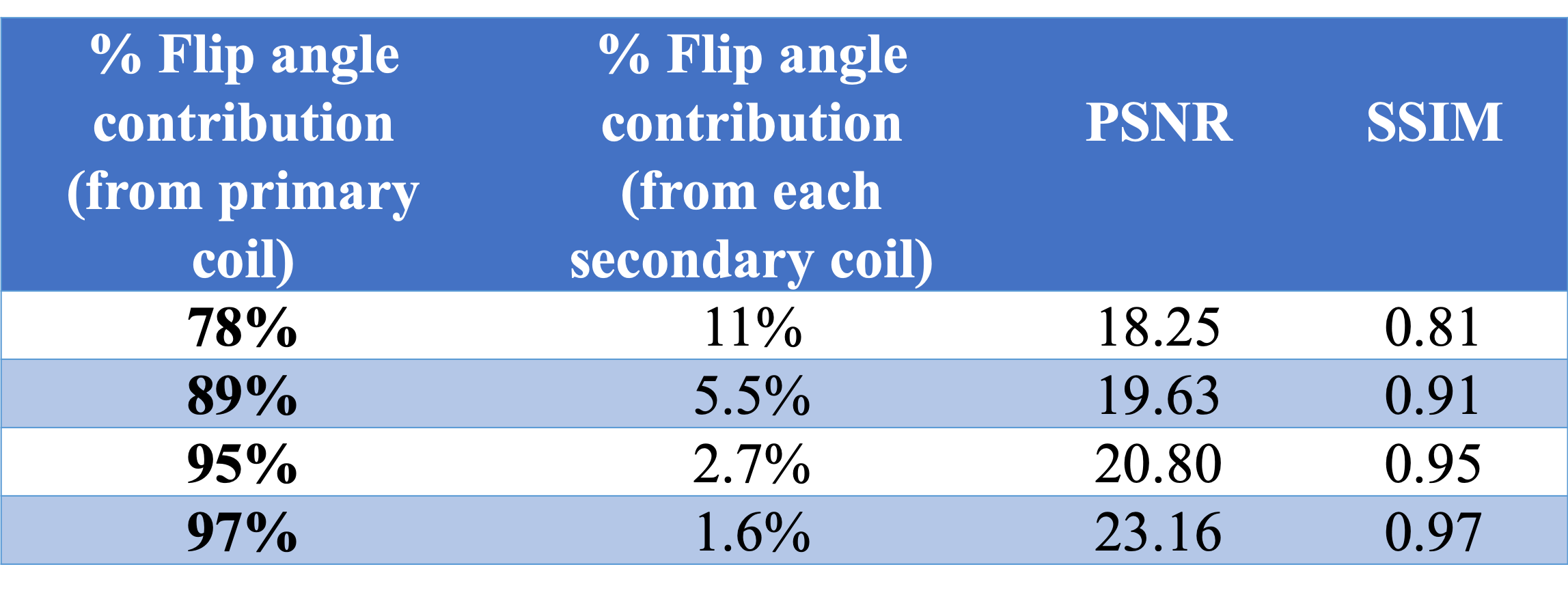
Transmit Array Spatial Encoding (TRASE) is a novel MRI technique that achieves spatial encoding by introducing phase gradients in the transmit RF magnetic field (B1). In this study, Bloch simulations were performed to investigate and study the effects of B1 field perturbations arising from inductive coupling among RF coils for 2D TRASE imaging. Simulations show that a flip angle contribution of ~95% or higher from the primary (driven) transmit coil is required for 2D TRASE MRI. This result is of crucial importance for designers of practical TRASE transmit array systems.
Introduction
Transmit Array Spatial Encoding (TRASE) is a spatial encoding technique in Magnetic Resonance Imaging (MRI) that uses phase gradients of the transmit radio-frequency (RF) B1 field1. TRASE is useful for spaceflight MRI systems since it no longer requires the use of complex B0 gradient coils, and can provide resolution at par with standard MRI2.TRASE relies on B1 fields of different phase gradients for k-space traversal. A TRASE pulse sequence uses RF pulses that are produced by switching between the transmit coils. However, field interactions among the RF coils can cause un-driven coils to produce unwanted B1 fields that impair the spatial encoding. Therefore, TRASE is sensitive to B1 field perturbations arising from inductive coupling between B1 transmit coils. Any B1 field isolation (coil decoupling) technique will require a clear understanding of the effects of the B1 field interactions that have never been studied for TRASE imaging.
The purpose of this study was to investigate the effects of B1 field coupling using Bloch3 simulations and determine the acceptable level of field interactions for 2D TRASE imaging.
Methods
Biot-Savart calculations (using the BSmag4 toolbox in Matlab) were used to generate B1 field maps to study the simplest 2D TRASE transmit coil setup consisting of 3 coils (1 uniform saddle coil and 2 phase gradient twisted solenoid5 coils). Various weighting factors, representing flip angle contributions from the secondary (un-driven) coils for each transmit pulse, were used to add the B1 field components of primary and secondary coil geometries to simulate coil coupling.The coupled B1 field maps were then used in a Bloch simulation program to perform 2D TRASE MRI simulations. The reconstructed 2D TRASE images from our simulations of varying levels of coil coupling were compared to that of an ideal case (i.e. no coupling between the RF transmit coils) by simple visual inspections and also by computing metrics such as PSNR (peak-signal-to-noise-ratio) and SSIM (structural-similarity-index)6.
Results
Figure 1 shows the contour maps for both coupled and un-coupled B1 fields of all the three transmit coil geometries considered for 2D TRASE.Some key observations about the effects of interacting B1 fields on 2D TRASE imaging are as noted below:
- Reduced phase gradient strength - impairs spatial resolution.
- A spatial shift in the phase gradient - causes a shifted image.
- Increased non-linearity of the phase gradients - causes object shape distortion in the image.
- Increased non-orthogonality of the phase gradients - impairs spatial encoding direction.
- A weak phase gradient induced in the uniform coil (that is supposed to have no phase gradient) - impairs spatial encoding.
- Increased |B1| inhomogeneity - causes large flip angle variation over the FOV.
A visual inspection of the above mentioned results in Figure 2 showed that a flip angle contribution of ~95% or higher is needed from the primary coil for image formation in 2D TRASE using the transmit coil setup described above.
Conclusion
Our results show that a flip angle contribution of ~95% or higher from the primary transmit coil is required for 2D TRASE MRI, using a 3-coil setup. This is a significant step in determining the acceptable levels of coil interactions that is conducive to 2D TRASE imaging. This permissible limit of B1 field interactions will be applicable to any 2D TRASE transmit coil setup of 3 coils.Currently, geometric decoupling is used between the transmit coils for 1D TRASE imaging7. If the B1 field isolation achieved from geometric decoupling alone, for any 2D TRASE transmit RF system, is not as good as the required permissible limit (as determined from this study), then alternate or additional means, such as the use of pin-diode switches, need to be employed to increase the isolation up to the required level. Therefore, the results of this study are important for designers of practical TRASE transmit array systems.
Acknowledgements
We acknowledge the funding provided by the Canadian Space Agency (CSA) FAST - Zero-G MRI Project grant to GES (Principal Investigator) titled “Suborbital Development and Testing of a Space Flight Astronaut Magnetic Resonance Imager”.
References
- J. C. Sharp and S. B. King, “MRI using radiofrequency magnetic field phase gradients,” Magnetic resonance in medicine, vol. 63, pp. 151-161, 2010.
- P. Bohidar, H. Sun, G. E. Sarty, J. C. Sharp, “TRASE 1D sequence performance in imperfect B1 fields,” Journal of Magnetic Resonance, vol. 305, pp. 77-88, 2019.
- F. Bloch, “Nuclear induction,” Physical review, vol. 70, p. 460, 1946.
- L. Quéval, “BSmag toolbox user manual,” Technical Report, Department of Electrical engineering, University of Applied Sciences Düsseldorf, Germany, April 2015. Available: http://www. lqueval.com
- H Sun, S Yong, J C. Sharp, “The twisted solenoid RF phase gradient transmit coil for TRASE imaging,” Journal of Magnetic Resonance, vol. 299, pp. 135– 150, 2019.
- Z. Wang, A. C. Bovik, H. R. Sheikh, E. P. Simoncelli, “Image quality assessment: from error visibility to structural similarity,” IEEE transactions on image processing, vol. 13.4, pp. 600-612, 2004.
- H. Sun, A. AlZubaidi, A. R. Purchase, J. C. Sharp, “A geometrically decoupled, twisted solenoid single‐axis gradient coil set for TRASE,” Magnetic resonance in medicine, pp. 1-15, 2019.
Figures
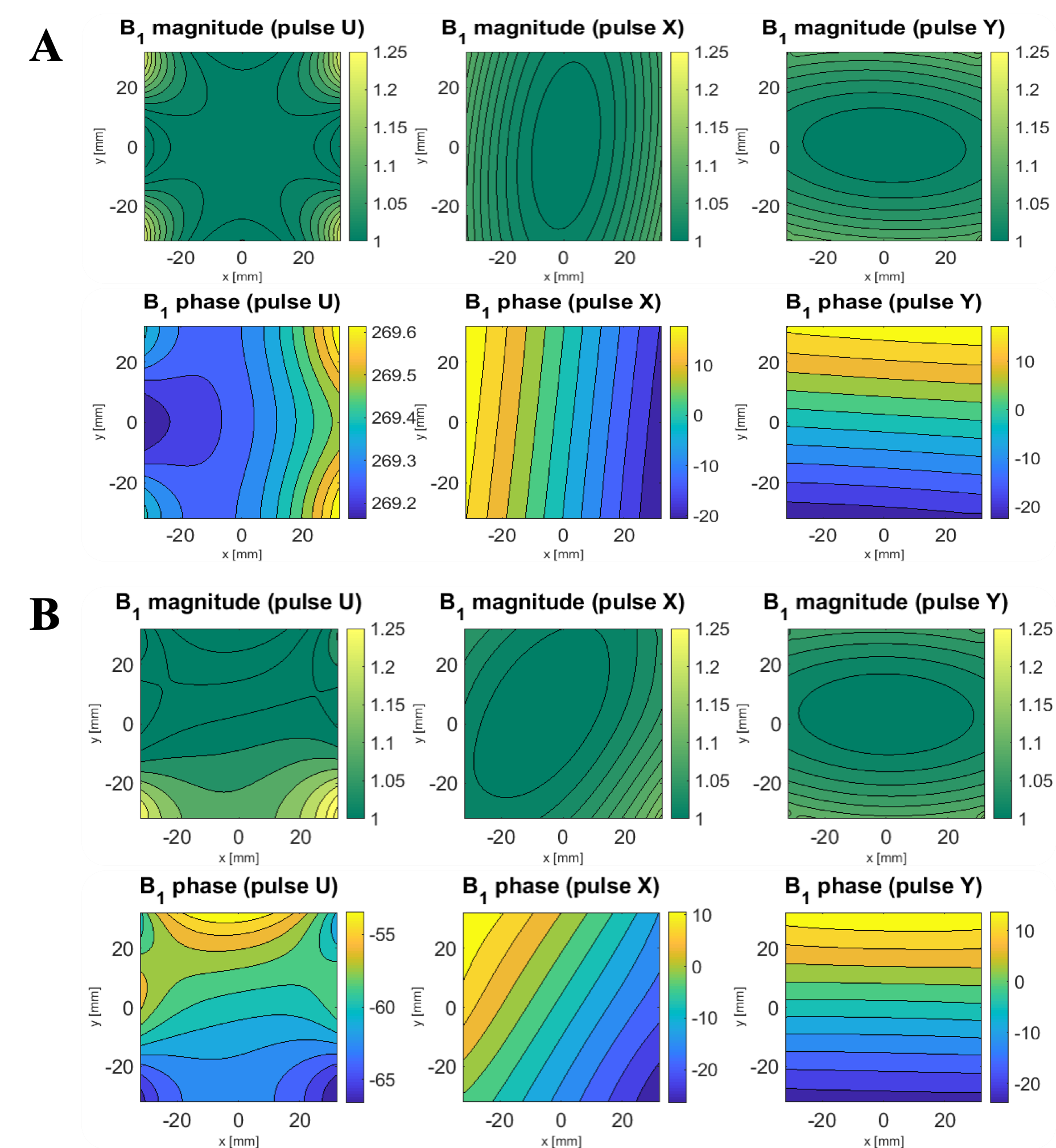
B1 field magnitude (normalized) and phase contour maps (generated from Biot-Savart simulations) of all the three transmit RF coil geometries (U=uniform saddle coil; X= twisted solenoid coil 1; Y= twisted solenoid coil 2) used in our 2D TRASE MR imaging, over a FOV of 64mm x 64mm for flip angle contributions from the primary coil: (A) 100% (no coupling) and (B) 78% (interaction from each secondary coil is 11%). Note that the contour maps of the B1 magnitude and phase for all three coils (U, X, and Y) are shown in different colour schemes for clarity.
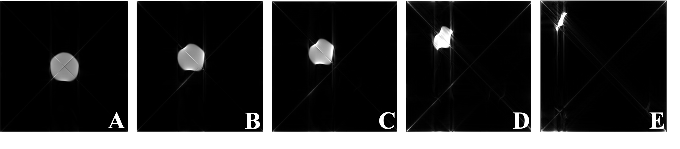
Reconstructed images of a circular object (64 mm diameter) from our 2D TRASE simulations using varying levels of flip angle contribution from the primary coil - (A) 100% (no coupling) (B) 97% (C) 95% (D) 89% and (E) 78%. As the levels of B1 field coupling increase from panel (B) to (E), the object shape distortions significantly dominate the simulated 2D TRASE images.