3696
Tailored 3D Inner Volume Suppression Pulses for MR Corticography1Biomedical Engineering, Vanderbilt University, Nashville, TN, United States, 2Department of Radiology and Radiological Sciences, Vanderbilt University Medical Center, Nashville, TN, United States, 3Athinoula A. Martinos Center for Biomedical Imaging, Massachusetts General Hospital, Charlestown, MA, United States
Synopsis
To fully utilize the potential of a new cortical imaging-optimized 7T scanner with Gmax= 200 mT/m & Smax=700 T/m/s gradients, 128 Rx channels, 16 Tx channels, and an AC/DC B0 shim array, we describe a tailored parallel transmit inner-volume-suppression (IVS) pulse design, which can enable highly accelerated functional and diffusion imaging by reducing g-factor and suppressing physiological noise from ventricle CSF. 3D IVS pulses were designed using simulated B1+ maps for the scanner’s 24-element coil. Simulation results demonstrated uniform inner volume suppression for 3D and 2D imaging. A 2D in-vivo IVS pulse design experiment demonstrated IVS’s ability to reduce g-factor.
Introduction
MR Corticography (MRCoG) is a developing imaging technique that will use inner volume suppression (IVS) to enable highly accelerated functional and diffusion imaging of the cortex, by reducing g-factor and suppressing physiological noise from ventricle CSF. A new 7T scanner is being developed for MRCoG with Gmax= 200 mT/m & Smax=700T/m/s gradient performance, 128 Rx channels, 16 Tx channels, and an AC/DC B0 shim array 1. Here we describe a tailored IVS parallel transmit pulse design for the scanner, which could be applied before each excitation and readout.Methods
RF pulses were designed for the 24-channel loop Tx array (Fig 1) that will be built for the system and compressed to 16 channels using acpTx 2, using B1+ maps that were simulated in a human head model using Ansys HFSS (Canonsburg, PA, USA). RF pulses were solved using a magnitude least-squares design that alternated between RF and target phase updates 3,4. Figure 2 shows the target pattern for pulse design which was an ellipse centered on the ventricles with AP/HF/LR semi axes of 4.8/3.2/3.2 cm. All voxels in the cerebrum were considered in the design, except for a transition band around the ellipse. Pulses were designed both to excite the entire ellipse which would be applied before 3D acquisition (“Joint”), and to excite only one slice at a time within the ellipse, while treating voxels within the ellipse but in other slices as “don’t care” regions (“Slice-by-Slice”), which could provide improved suppression for 2D acquisitions. Both designs targeted zero excitation in voxels in the cerebrum but outside the ellipse. We also adapted a highly parallelizable k-space-based parallel transmit pulse design that has low memory and computational requirements 5. A 7 ms SPINS trajectory 6 with 0.67 cm max resolution was designed for the pulse subject to the scanner’s gradient amplitude and slew rate constraints (Fig 3). To demonstrate the value of the scanner’s gradient performance, we also designed 7 ms pulses with conventional Gmax= 40 mT/m & Smax=200 T/m/s gradient limits, which reached the same spatial resolution but required higher excitation k-space undersampling. To demonstrate the potential value of the AC/DC array, pulses were also designed using an ideal B0 shim pattern in which the target suppressed region was on-resonance and everywhere else was 500 Hz off-resonance.To demonstrate how IVS enables highly accelerated imaging with low g-factor, we designed a patient-tailored 8-Tx-channel 2D IVS pulse for a healthy subject, on a Philips 7T Achieva scanner (Philips Healthcare, Cleveland, Ohio, USA). The target pattern was an ellipse covering the ventricles in a mid-brain transverse slice, with 4.9/2.8 cm semi-axes in the AP/LR dimensions. The excitation trajectory was a 9.3 ms 2D spiral with 2x undersampling and 1 cm max resolution. The RF pulse was solved using the iterative magnitude least-squares design and the B1+ maps measured in the human subject. The target pattern matrix had resolution 3.5 mm. The designed excitation pulse was played immediately before a gradient spoiler and a non-selective excitation pulse, followed by a 3D gradient-recalled echo sequence. 32-channel receive sensitivity maps were calculated with and without the IVS pulse, and those 120-by-96 receive sensitivity maps were used to calculate g-factor maps for R=2x, 4x, 6x, and 8x uniform undersampling in the LR dimension.
Results
Figure 4 shows that the joint design achieved 11.87% NRMSE, compared to 26.97% NRMSE with conventional gradient specifications. Most of the errors appeared at the edges of the transition band, with other errors lower than 5% of the target flip angle. The k-space-based design gave similar performance with the spatial domain method, except for the edges of the transition band. The slice by slice design reduced the NRMSE to 4.75%. The ideal B0 shift further reduced the NRMSE to 4.40% and 2.31% for the joint design and slice by slice design, respectively. Figure 5a shows the in-vivo sum-of-squares images with and without IVS. Figure 5b lists the simulated 1/g maps and SNR-gain maps with different acceleration factors. IVS improved SNR in locations where the inner-volume would alias, to the left and right of the region. Figure 5c lists the mean and max g-factors for each acceleration factor.Conclusion
We have proposed a new tailored parallel transmit pulse design for inner volume suppression in MRCoG, utilizing the MRCoG scanner’s high performance gradients, 24-element Tx array, and AC/DC B0 shim coils. Simulation results demonstrated uniform inner volume suppression while maintaining the outer volume intact, which can in turn decrease g-factor in highly accelerated imaging.Discussion
In future work, we will numerically optimize the excitation trajectory 7, apply acpTx to compress the array to the scanner’s 16 channels 2, jointly optimize realistic AC/DC shim coil patterns with the RF pulse, and verify g-factor improvements.Acknowledgements
This work was supported by NIH grants U01 EB 025162 and R01 EB 016695.References
1. Stockmann, Jason P., et al. "A 32‐channel combined RF and B0 shim array for 3T brain imaging." Magnetic Resonance in Medicine 75.1 (2016): 441-451.
2. Cao, Zhipeng, Xinqiang Yan, and William A. Grissom. "Array‐compressed parallel transmit pulse design." Magnetic Resonance in Medicine 76.4 (2016): 1158-1169.
3. Grissom, William, et al. "Spatial domain method for the design of RF pulses in multicoil parallel excitation." Magnetic Resonance in Medicine 56.3 (2006): 620-629.
4. Setsompop, Kawin., et al. "Magnitude least squares optimization for parallel radio frequency excitation design demonstrated at 7 Tesla with eight channels." Magnetic Resonance in Medicine 59.4 (2008): 908-915.
5. Grissom, William. k-Space Domain Parallel Transmit Pulse Design. In Proceedings of the 26th Annual Meeting of ISMRM, Paris, France, 2018. Abstract 3396.
6. Malik, Shaihan J., et al. "Tailored excitation in 3D with spiral nonselective (SPINS) RF pulses." Magnetic Resonance in Medicine 67.5 (2012): 1303-1315.
7. Davids, Mathias, et al. "Fast three‐dimensional inner volume excitations using parallel transmission and optimized k‐space trajectories." Magnetic resonance in medicine 76.4 (2016): 1170-1182.
Figures
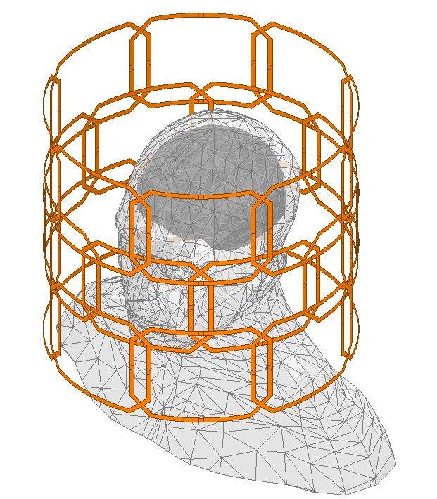
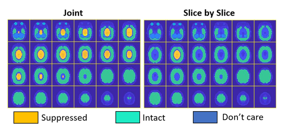
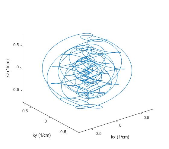
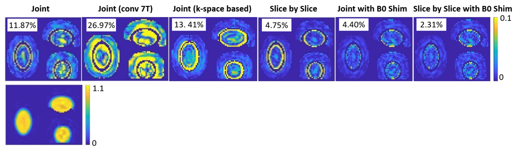
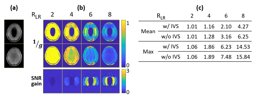
Fig 5: (a) In-vivo sum-of-squares images w/ and w/o subject-tailored IVS (Tx=8).
(b) 1/g maps of R=2,4,6,8 in the LR dimension (Rx=32), and the maps of SNR gain. IVS lowered g-factor and therefore improved SNR in locations where the inner-volume would alias, to the left and right of the region.
(c) Mean and max g-factors for each acceleration factor.