3694
Fully embedded parallel transmission: Stable performances using universal pulses with fast online customization1Institute of Neuroradiology, University Hospital Erlangen, Erlangen, Germany, 2SIEMENS Healthineers, Erlangen, Germany, 3Institute of Radiology, University Hospital Erlangen, Erlangen, Germany, 4Friedrich Alexander University Erlangen Nürnberg, Erlangen, Germany, 5Institute of Medical Physics, Friedrich Alexander University Erlangen Nürnberg, Erlangen, Germany
Synopsis
To homogenize signals 7 Tesla MRI reliably and fast, a pTx pulse design process was established. Trajectory, energy regularisation parameter and universal pulse shapes were calculated by solving global optimization problems using a dataset of 12 subjects (B1+ profiles, B0, VOP). Pulse shaping is done online using the actual subject‘s data acquired during the sequence preparation phase which lasts about 90s. A fitting curve for SED is also provided which, combined with online calculated SED values, aims to use the full amount of tolerable SAR. Compared with the CP-Mode, the NRMSE could be substantially improved for all 36 volunteers.
Introduction
Ultra-High Field (UHF) MRI has to cope with inhomogeneous B1 fields causing signal variations throughout the brain. To foster clinical translation of UHF MRI, a fast dynamic parallel transmit (pTx) pulse design is desirable. Here we present an approach that uses a predefined transmit k-space trajectory and a corresponding parameter set enabling individual radiofrequency frequency (RF) pulse shaping. The proposed algorithm was implemented to design nonselective pTx excitation pulses for a 3D MPRAGE sequence.Methods
The pTx pulses are based on a spiral nonselective (SPINS) k-space trajectory presented in [1], yet with additional parameters. In spherical coordinates (kr, kΦ, kφ as radial, polar and azimuthal components) its definition is:$$ k_r(t) = \frac{k_{max}}{1+e^{\alpha (\frac{t}{T}-\beta)}+e^{\gamma ((\frac{t}{T})^2-\delta)}} $$
$$ k_\theta(t) = \theta_0 + \theta't+ \theta''t^2 $$
$$ k_\phi(t) = \phi_0 + \phi't+ \phi''t^2$$
T = 1ms denotes the pulse duration, the other parameters define the shape of the k-space trajectory (kmax,α,β,γ,δ,Φ0, Φ',Φ'',φ0,φ',φ''). After transformation into Cartesian coordinates the z component kz (head foot direction) is scaled with a constant factor cz. All trajectory parameters, combined with a regularization parameter for the pulse energy λ0 used for pulse shaping, are defined as ‘Combined Optimization Values’ (COV):
$$ COV :=[k_{max},\alpha, \beta, \gamma, \delta, \theta_0,\theta',\theta'',\phi_0, \phi', \phi'', c_z, \lambda_0] $$
The problem - formulated to determine the most suitable COV - uses Np=12 previously acquired data sets, namely B1+, B0 maps and virtual observation points (VOPs) containing specific absorption rate (SAR) information based on [2]. For every combination of COV, the online RF shape optimization process and a Bloch simulation were performed for all data sets returning individual values for normalized root mean square error (NRMSE) of the flip angle (FA) and maximum local specific energy dose (SED) in [J/kg] which are used as cost:
$$min∑_{p=1}^{N_p}[w_{Hom} e^{NRMSE_p(COV)}+ w_{SED} e^{SED_p(COV)}]$$
This approach uses two different weights wHom for homogeneity of the resulting FA distribution and wSED for the SED. After an optimized set COVopt was found, corresponding universal pulse shapes b0,COVopt for each coil are generated similarly:
$$min∑_{p=1}^{N_p}[w_{Hom} e^{NRMSE_p(b_{0,COVopt})}+ w_{SED} e^{SED_p(b_{0,COVopt})}]$$
For a given set of COVopt and b0,COVopt, the parameter λ0 is varied and for each value the NRMSE and maximum local SED values are calculated. So a mean SEDCOVopt(λ) curve of all subjects can be fitted. Given the SAR limits formulated by IEC, sequence protocol parameters and all other pulse shapes, one can formulate a limit for the maximum specific energy dose (SEDlim) of the pTx excitation pulse. During the online pulse preparation process, λ can be adjusted using the fitted curve updated with online SED values.
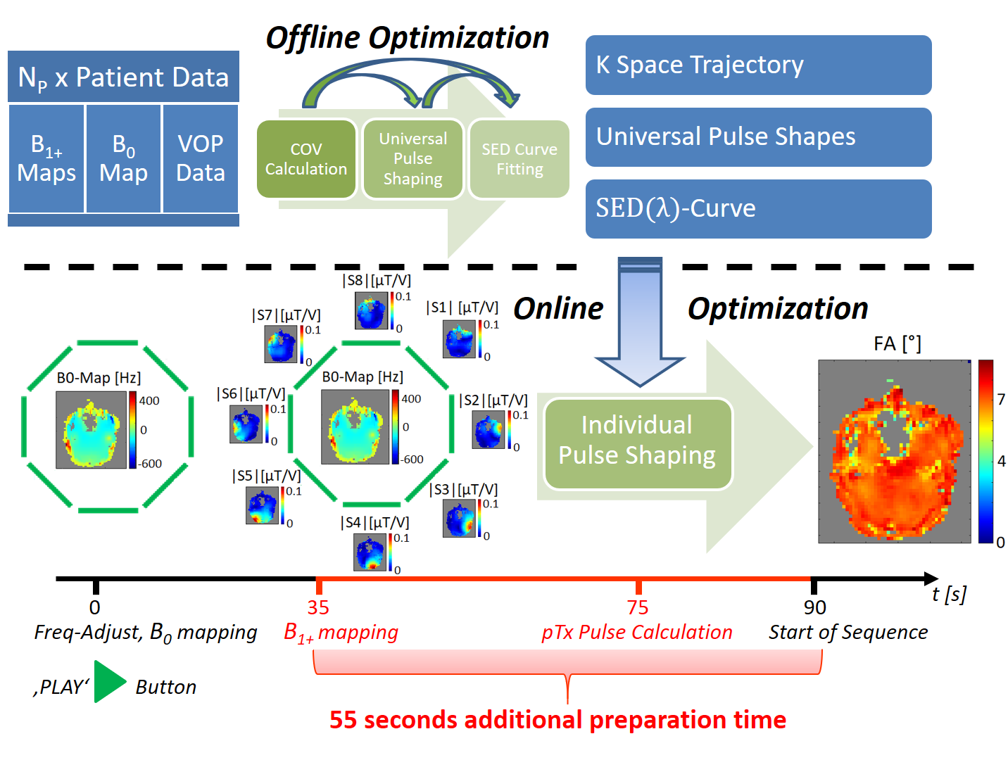
The pTx pulse design was implemented on a 7-Tesla whole-body MR system (Magnetom Terra, Siemens Healthineers, Erlangen, Germany). An 8Tx/32Rx head coil (Nova Medical, Wilmington, USA) was used for measurements. Those were performed on 12 healthy European, 12 healthy Asian and 12 European subjects with anomalies or pathological conditions including arachnoid cysts, multiple sclerosis lesions, cavernomas, meningiomas or parenchyma defects. B1+ mapping was performed using a magnetization prepared saturation recovery turbo flash sequence (TAq = 40s) [3]. B0 mapping was done with a sagittal oriented gradient echo sequence (TE1 = 2.39s, TE2 = 4.59s, TE3 = 7.09s; 4x4x6mm3; TAq = 12s). A mask was generated cutting off low intensity voxels. The duration of the sequence preparation phase was 90s. In this time, frequency adjustment, B0 mapping, B1+ mapping and individual RF pulse shaping were performed. Figure 1 shows the schematic workflow of designing COV based pTx pulses. It was used in a 3D-MPRAGE sequence enabling 0.65mm isotropic resolution. Following parameters were applied: TR = 3s, TI = 1.1s, TE = 2.92ms in circularly polarized (CP) mode and 3.37ms in pTx-Mode, matrix size: 384x336x256, FoV = 250x218.75x167mm3, 256 excitation pulses (FA=7°) per TR, echo spacing of 7.4ms in CP and 7.8ms in pTx mode. With a sampling rate of 100kHz, altogether 800 pulse shape samples were optimized online with the variable exchange algorithm [4]. Two sets of COV, corresponding universal pulse shapes and SED curves were calculated with two different relative weightings [wHom, wSED], such as [5,1] and [1,1]. Consequently they are called IOP51, IOP11, UP51 and UP11 depending on whether they are individually optimized online (IOP) or used as universal pulses (UP) which were introduced in [5]. Default B0 shim currents were applied in all measurements.
Results and Discussion
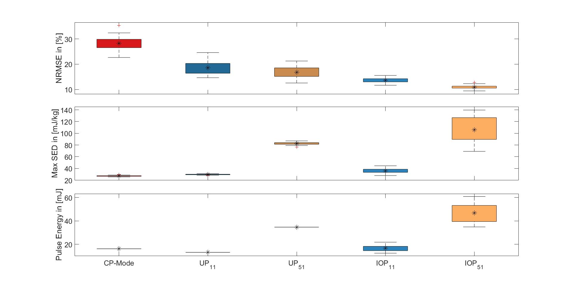
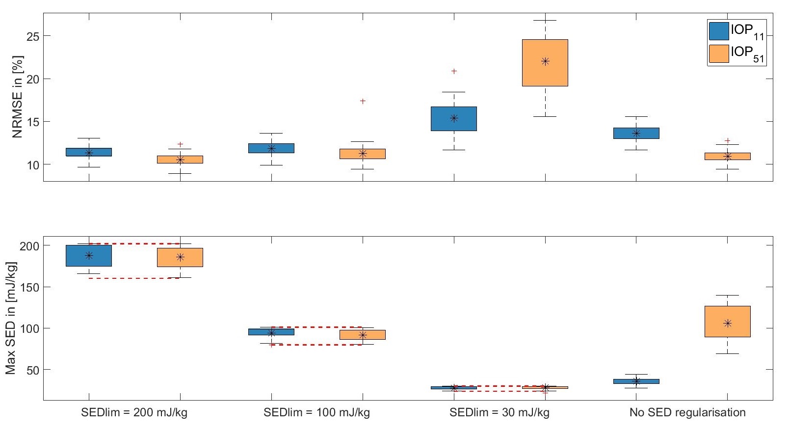
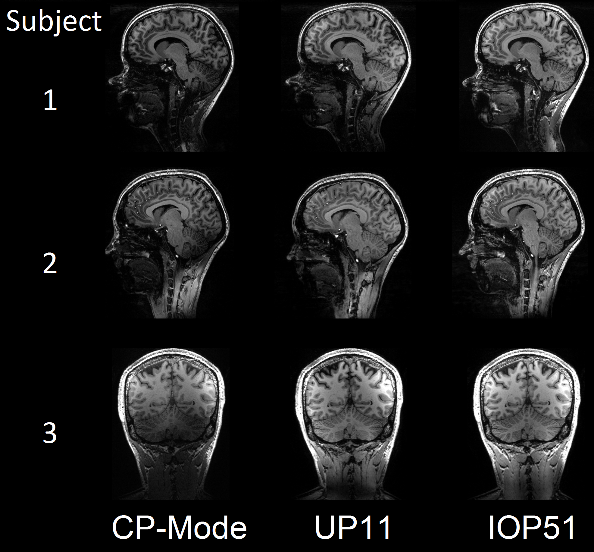
All pTx pulses resulted in decreased FA-NRMSE (figure 2). There is a significant difference (p<0.05) in NRMSE and SED for the IOP51 between the 'European' and ‘European with anomalies’ group, yet no such differences were found for all other groups and pulses. Figure 3 shows performance of IOPs with online SED regularization for different limits. It is indicating a better performance of pulses whose initial SED distributions are closer to the given SED limits.Figure 4 shows MPRAGE images using CP-Mode pulses, UP11 or IOP51 without SED regularization as excitation pulses and an adiabatic inversion pulse. Three study participants (f25, f27, m37) were depicted as showcases.
Conclusion
A fast and robust routine was demonstrated designing pTx pulses adapted to the subject specific maps acquired in the sequence preparation phase. Compared to the CP-Mode, the FA-NRMSE was substantially lower while SED exposure remained controllable.Acknowledgements
No acknowledgement found.References
1. Malik, S.J. et al., Tailored excitation in 3D with spiral nonselective (SPINS) RF pulses. Magn Reson Med, 2012. 67(5): p. 1303-15.
2. Eichfelder, G. and M. Gebhardt, Local specific absorption rate control for parallel transmission by virtual observation points. Magn Reson Med, 2011. 66(5): p. 1468-76.
3. Fautz, H.-P. et al. B1 mapping of coil arrays for parallel transmission. in ISMRM 16. 2008. Toronto.
4. Setsompop K et al. Magnitude least squares optimization for parallel radio frequency excitation design demonstrated at 7 Tesla with eight channels. Magn Reson Med 2008. 59(4): p. 908–915.
5. Gras, V., et al., Universal pulses: A new concept for calibration-free parallel transmission. Magn Reson Med, 2017. 77(2): p. 635-643.
Figures