3693
Inversion Pulses with B1-Robustness and Reduced Energy by Optimal Control
Christina Graf1, Christoph Stefan Aigner2, Armin Rund3, Andreas Johann Lesch1, and Rudolf Stollberger1
1Institute of Medical Engineering, Graz University of Technology, Graz, Austria, 2Physikalisch-Technische Bundesanstalt (PTB), Braunschweig and Berlin, Germany, 3Institute of Mathematics and Scientific Computing, University of Graz, Graz, Austria
1Institute of Medical Engineering, Graz University of Technology, Graz, Austria, 2Physikalisch-Technische Bundesanstalt (PTB), Braunschweig and Berlin, Germany, 3Institute of Mathematics and Scientific Computing, University of Graz, Graz, Austria
Synopsis
The aim of this work is to design slice-selective inversion RF pulses that are robust among $$$B1$$$-variations while the pulse energy is reduced. For that purpose, an optimal control framework based on an ensemble formulation is introduced. The numerically optimized RF pulses showed an excellent performance compared to the target magnetization for a broad range of $$$B1$$$-scalings. Phantom measurements were performed using a 32 channel head coil for receive and a birdcage body coil for transmit and revealed excellent inversion profiles.
Introduction
There is still a substantial demand for radio frequency pulses that achieve robust flip angles among RF field inhomogeneities with well defined slice profile quality, especially at higher field strengths of $$$3T$$$ or more. A family of RF pulses that fulfill the requirement of $$$B1$$$-robustness are adiabatic pulses1 or composite RF pulses2. However, the main limitation for this class is the requirement of a higher RF energy3. By using optimal control it could be shown that it is possible to optimize the properties of SMS refocousing pulses with respect to RF-energy, hardware constraints and duration4,5,6. In this work we have used optimal control with an ensemble formulation for the specific aim of $$$B1$$$-robustness of slice selective inversion pulses with reduced RF energy. This optimized pulses are validated by phantom measurements on a $$$3T$$$ MR scanner.Theory
Aim of the robust optimization is to generate RF pulses with good performance over varying $$$B1$$$-field scaling. Therefore, we define the cost function as \begin{align*} J=\frac{1}{2} \sum \limits_{n=1}^{N} p_n\left( \int \limits_{\Omega} \left(M_{n}-M_{d}\right)^{2}d \Omega\right) + \frac{\alpha}{2} \int \limits_{0}^{T} \left( B1(t)\right)^{2} dt. \end{align*} Therein, the first term measures the slice profile accuracy as a weighted sum over the magnetization states $$$M_n$$$ for different $$$B1$$$-scalings, which is vital for achieving robustness of the optimized pulses7,8. A discrete probability distribution of the $$$B1$$$-scalings is assumed with $$$n=1 \cdots N$$$ instances with probability $$$p_n$$$ with $$$\sum \limits_{n=1}^{N} p_n=1$$$. $$$M_{d}$$$ is the desired slice profile over the spatial domain $$$\Omega$$$. The latter term in the cost functional allows for the simultaneous reduction of pulse energy with weighting parameter $$$\alpha>0$$$. The Bloch equations are solved numerically using a symmetric operator splitting9 which allows for the inclusion of relaxation effects. The optimization itself is based on a trust-region, semi-smooth quasi Newton method5,10, where the derivatives are supplied by using adjoint calculus11 combined with exact discrete derivatives.Methods
The above described problem is implemented in MATLAB (The MathWorks, Inc., Natick, USA). The desired state is chosen as rectangular slice with a total pulse time of $$$T=3.5 ms$$$. The iterative optimization is started from a GOIA-RF and slice-selective gradient shape based on 8th and 4th order hyperbolic secant functions12. The RF phase is computed by numerical integration for a bandwidth of $$$10kHz$$$13. The peak $$$B1$$$-amplitude of the GOIA pulse was intentionally scaled to $$$15.9\mu T$$$ to introduce $$$B1$$$-variations. The relaxation times are set to $$$T_{1}=102ms$$$ and $$$T_{2}=81ms$$$ which originate from the phantom used in the experimental validation. $$$B1$$$-robustness shall be optimized for a range of $$$70\%$$$ to $$$150\%$$$. A uniform discrete probability distribution of $$$B1$$$ is applied, where $$$N=9$$$ steps are chosen ($$$70\%$$$, $$$80\%$$$, …). The optimized inversion pulse is implemented as a preparation pulse with $$$TI=6.36ms$$$ in a FLASH sequence on a $$$3T$$$ MR Scanner (Magnetom Skyra, Siemens Healthcare, Erlangen, Germany). For validation of the simulations, high-resolution phantom scans were acquired ($$$TR/TE= 700/9.4ms$$$, $$$FOV= 150mm$$$, matrix$$$= 512 \times 256$$$). We used a Siemens 32 channel head coil for receive and the birdcage body coil for transmit. To analyze the robustness the magnitude of the inversion pulse was scaled from $$$50\%$$$ to $$$130\%$$$. Furthermore, we analyze the accuracy of the slice profile in terms of the root-mean-square deviation (RMSD) and the maximum deviation (maxDEV). For this purpose, the deviations of the optimized slice profiles from the desired one are calculated for each scaling of $$$B1$$$ and are used to calculate RMSD and maxDEV.Results and Discussion
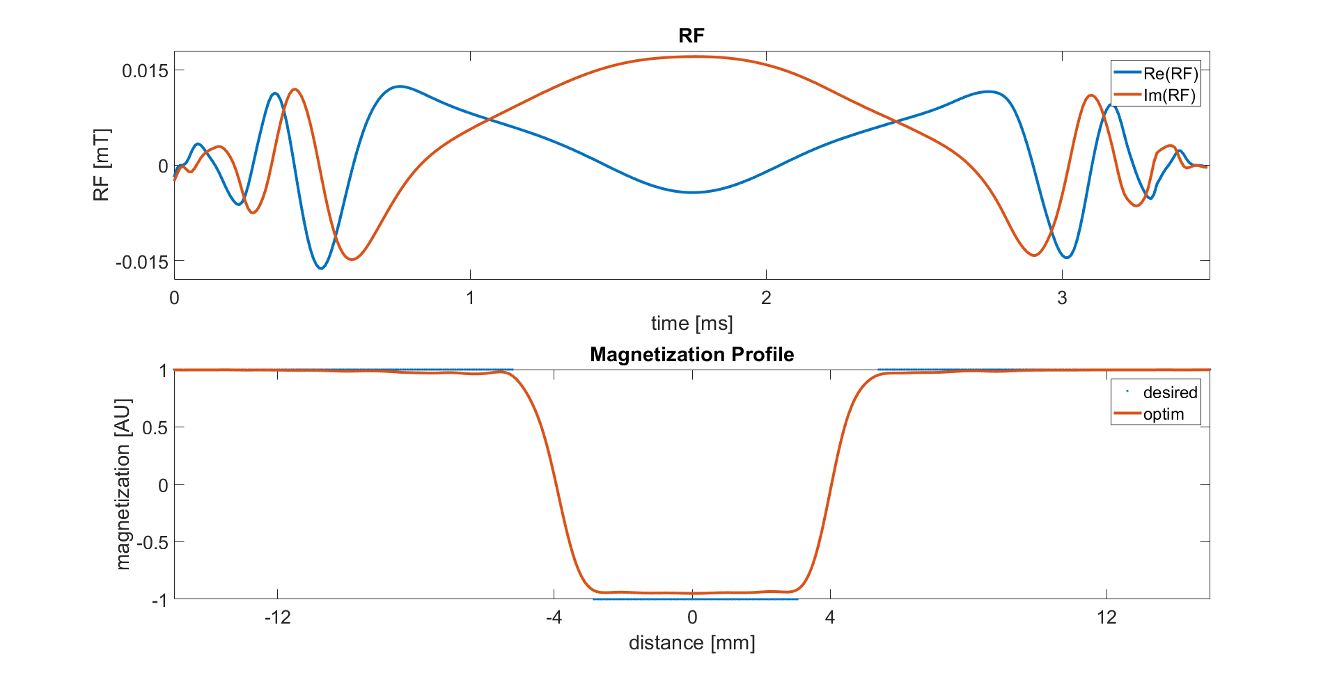
Figure 1 depicts the optimized complex RF pulse and the desired slice profile combined with the optimized slice profile. Figure 2 shows slice profile simulations for the reference and the optimized RF pulse for a broad set of $$$B1$$$-values. It can be seen clearly that the slice profile was substantially improved within the optimized $$$B1$$$-range of $$$70\%$$$ to $$$150\%$$$. The simulations further indicate robustness beyond the optimized range up to $$$200\%$$$ $$$B1$$$. In Figure 3, again, the optimized pulse results in accurate slice profiles across different $$$B1$$$-scalings. Table 1 lists key parameters of both RF pulses. Despite peak $$$B1$$$ increase of around $$$10\%$$$ of the optimized RF, the normalized power integral is decreased by approximately $$$40\%$$$. The RMSD is reduced to $$$0.182$$$ during optimization which represents the excellent slice-profile quality in Figures 2 and 3. Moreover, the maxDEV is reduced to $$$0.077$$$. In Figure 4 we see the measured inversion profiles for different scalings of $$$B1$$$. Due to amplifier constraints the maximal possible scaling factor was $$$130\%$$$. Note that the scaling of $$$50\%$$$ was not included in optimization, but still shows a nice slice profile. Out-of-slice a modulation of the receive profiles can be observed leading to a signal increase away from isocenter. In addition, simulations were carried out to further improve the slice profile beyond the one shown here. It turned out that such an improvement and simultaneous pulse robustness is possible, but only at the price of a pulse energy rising again.Conclusion
We optimized slice selective inversion pulses that are robust among $$$B1$$$-inhomogeneities paired with a reduced pulse energy. Over the $$$B1$$$-scaling range the maximum deviation from the desired slice profile was heavily reduced to $$$7.7 \%$$$. Further optimization can include $$$B0$$$-inhomogeneities as well as specific requirements on the RF.Acknowledgements
No acknowledgement found.References
- Matt A. Bernstein, Kevin F. King, Xiaohong Joe Zhou. Handbook of MRI Pulse Sequences. Elsevier Academic Press, 2004.
- Jay Moore, Marcin Jankiewicz, Huairen Zeng, Adam W. Anderson, John C. Gore. Composite RF pulses for B1+-insensitive volume excitation at 7 Tesla. Journal of Magnetic Resonance, 2010.
- Michael Garwood, Yong Ke. Symmetric Pulses to Induce Arbitrary Flip Angles with Compensation for RF Inhomogeneity and Resonance Offsets. Journal of Magnetic Resonance, 1991.
- Christoph Stefan Aigner, Christian Clason, Armin Rund, Rudolf Stollberger. Efficient high-resolution RF pulse design applied to simultaneous multi-slice excitation. Journal of Magnetic Resonance, 2016.
- Armin Rund, Christoph Stefan Aigner, Karl Kunisch, Rudolf Stollberger. Magnetic Resonance RF pulse design by optimal control with physical constraints. IEEE Transactions on Medical Imaging, 2018.
- Armin Rund, Christoph Stefan Aigner, Karl Kunisch, Rudolf Stollberger. Simultaneous multislice refocusing via time optimal control. Magnetic Resonance in Medicine, 2018.
- Eric Van Reeth, Helene Ratiney, Olivier Beuf, Soukaina Kanice, Steffen J. Glaser, Dominique Sugny. BEEEP: B1-robust Energy Efficient Excitation Pulses. In Proceedings of the International Society of Magnetic Resonance in Medicine (ISMRM), 2019.
- Eric Van Reeth, Helene Ratiney, Kevin Tse Ve Koon, Michael Tesch, Denis Grenier, Olivier Beuf, Steffen J. Glaser, Dominique Sugny. A simplified framework to optimize MRI contrast preparation. Magnetic Resonance in Imaging, 2018.
- Christina Graf, Armin Rund, Christoph Stefan Aigner, Karl Kunisch and Rudolf Stollberger. Simulation of Bloch and Bloch-McConnell equations – speed and accuracy. In Proceedings of the International Society of Magnetic Resonance in Medicine (ISMRM), 2019.
- Florian Mannel, Armin Rund. A Hybrid Semismooth Quasi-Newton Method Part 1: Theory. SFB-Report 2018-005, Graz, 2018. https://imsc.uni-graz.at/mobis/publications/SFB-Report-2018-005.pdf
- Fredi Tröltzsch. Optimal Control of Partial Differential Equations: Theory, Methods and Applications. American Mathematical Society, 2010.
- Alberto Tannus, Michael Garwood. Adiabatic pulses. NMR in Biomedicine, 1998.
- Ovidiu C. Andronesi, Saadallah Ramadan, Eva-Maria Ratai, Dominique Jennings, Carolyn E. Mountford, A. Gregory Sorensen. Spectroscopic Imaging with Improved Gradient Modulated Constant Adiabadicity Pulses on High-Field Clinical Scanners. Journal of Magnetic Resonance, 2011.
Figures
Figure
1. Optimized complex RF pulse in $$$mT$$$ over a time horizon of
$$$3.5ms$$$ (top).
The discretization step length is $$$\tau = 0.01 ms$$$. Depicted at
the bottom
are the desired and the optimized slice profile of the
$$$z-$$$magnetization.
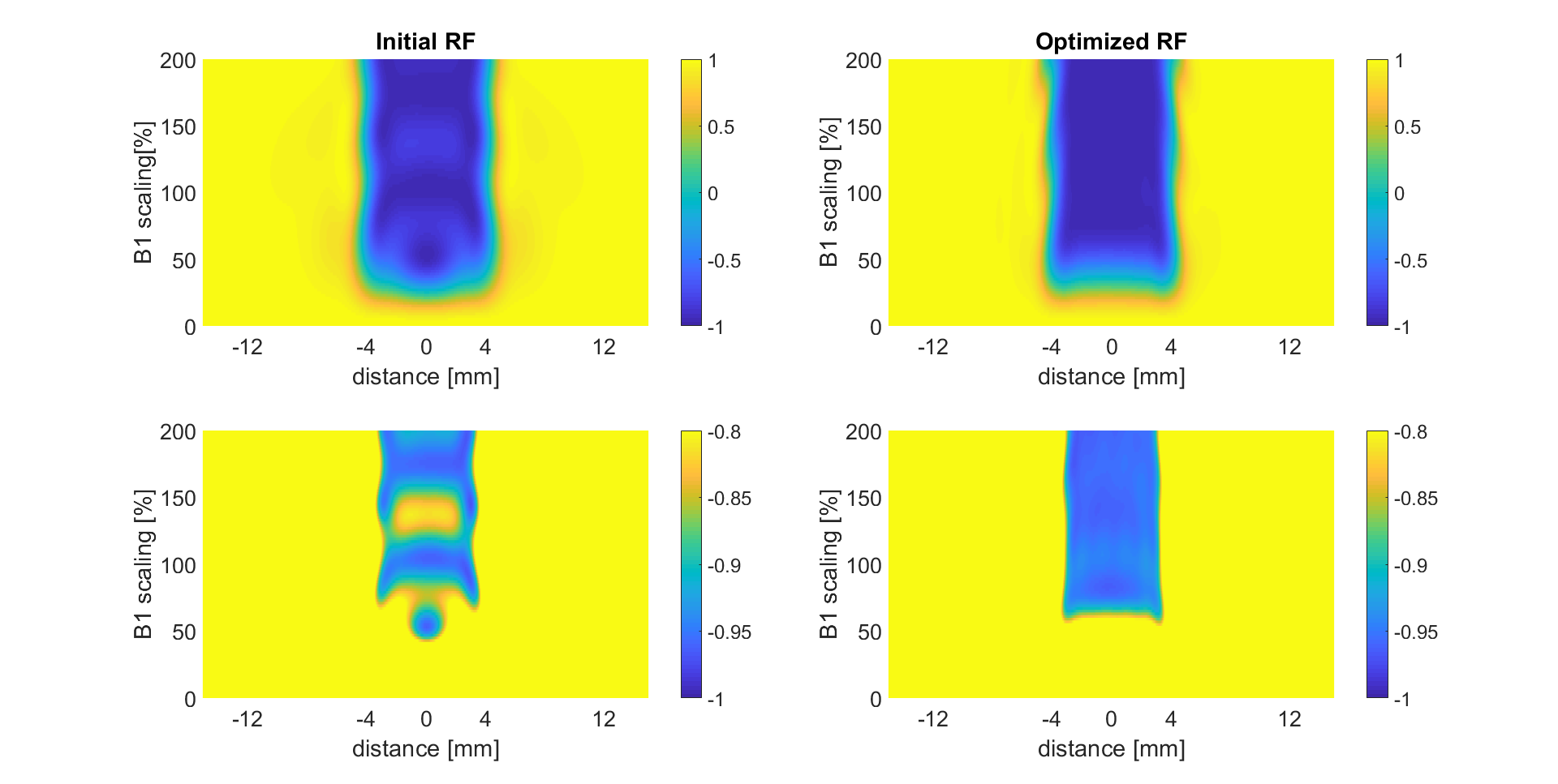
Figure
2. z-coordinate of the magnetization vector for different scalings of
$$$B1$$$ in $$$\%$$$ for the initial RF pulse (left) and optimized RF
pulse (right). The magnetization is scaled from $$$-1$$$ to $$$1$$$
(top) and $$$-1$$$ to $$$-0.8$$$ (bottom).
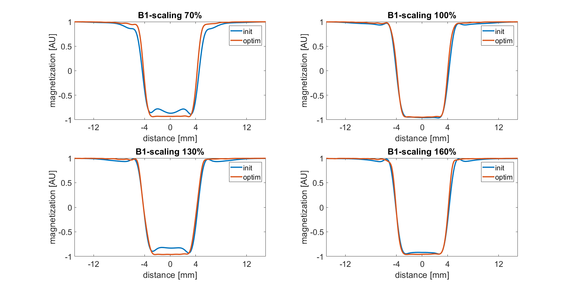
Figure 3. $$$z$$$-magnetization
in a.u. of the initial and the optimized RF pulse for different
scalings of the $$$B1$$$ amplitude ($$$70 \%$$$, $$$100 \%$$$, $$$130
\%$$$ and $$$160 \%$$$).
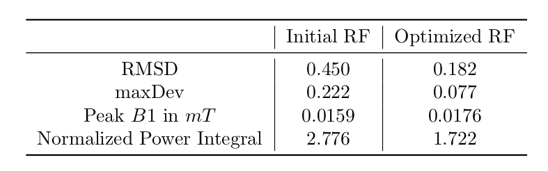
Table 1.
Key parameters for the initial RF (left) and
optimized RF (right). The first 2 lines characterize the quality of
the slice profile, the second two lines the peak amplitude and the normalized power integral.
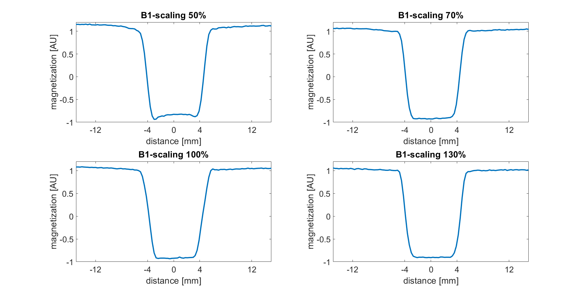
Figure 4.
Validation
on the MR scanner. Inversion profiles are shown for $$$B1$$$ scalings
of $$$50 \%$$$, $$$70 \% $$$, $$$100 \% $$$ and $$$130 \%$$$. The
scaling factor of $$$50\%$$$ was not included in the optimization
process.