3511
CNN-based segmentation of vessel lumen and wall in carotid arteries from T1-weighted MRI1Charité - Universitätsmedizin Berlin, Berlin, Germany, 2Fraunhofer MEVIS, Bremen, Germany, 3Department of Radiology, Medical Center - University of Freiburg, Faculty of Medicine, Freiburg, Germany, 4Department of Neurology, Medical Center – University of Freiburg, Faculty of Medicine, Freiburg, Germany
Synopsis
Internal carotid artery stenosis is a major source of ischemic stroke. Multi-contrast MRI can be used for assessing wall characteristics and plaque progression. The quantification of vessel wall morphology requires an accurate segmentation of the vessel wall. To reduce inter- and intra-observer variability, we aim to provide a fully automatic segmentation method. Our approach for segmenting the lumen and vessel wall of the extracranial carotid arteries in T1-weighted 3D MR images is based on a 2D convolutional neural network. Average dice coefficients were 0.947/0.859 for the lumen/vessel wall and the median Hausdorff-distance was below the voxel-size of 0.6mm for both.
Introduction
Internal carotid artery stenosis is a major source of ischemic stroke. Therapy planning is usually based on the assessment of vessel characteristics like wall thickness and degree of stenosis, which can be estimated from black-blood MRI 1. This requires an accurate segmentation of the vessel wall. Due to intensity inhomogeneities this task can be challenging. Fully automatic segmentation is desirable as manual delineations are subject to inter and intraobserver variation. In this work we present an approach for segmenting the lumen and vessel wall of the extra-cranial carotid arteries based on a 2D convolutional neural network in T1-weighted 3D MR images.Methods
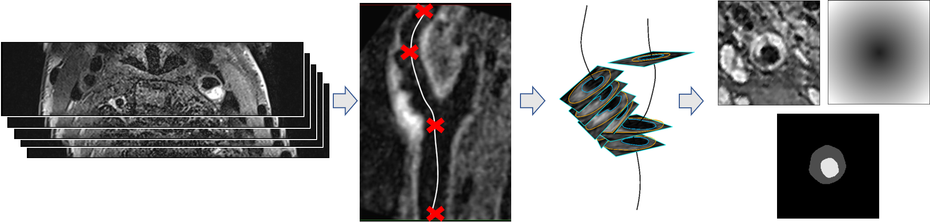
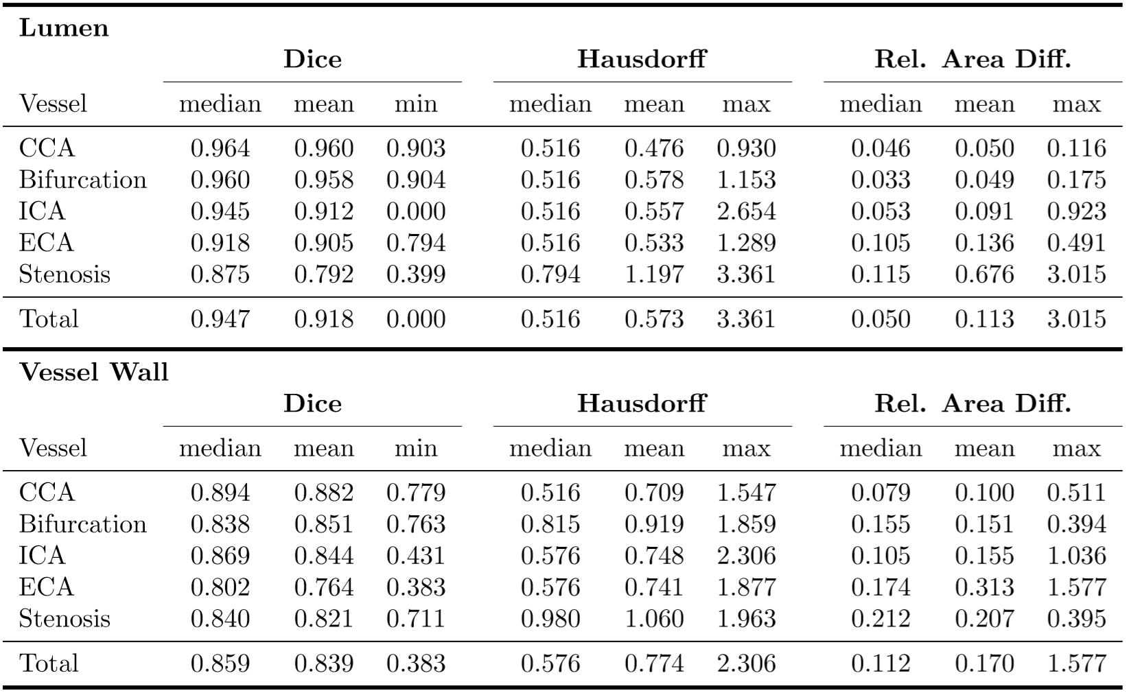
MR data was acquired from 121 patients suffering from atherosclerotic plaques including T1-weighted 3D images after informed consent. A variable flip angle TSE sequence (Sampling Perfection with Application optimized Contrasts using different flip angle Evolution - SPACE) with fat saturation and dark-blood preparation was applied2. Imaging was done on a 3T Prisma (Siemens Healthineers, Erlangen, Germany) with an 8-channel surface (NORAS MRI products GmbH, Hoechberg Germany). An isotropic spatial resolution of 0.6 mm was used. The 3D image volume covered the carotid artery around the bifurcation including the common carotid artery (CCA), internal carotid artery (ICA) and external carotid artery (ECA).The preprocessing pipeline is shown in Fig. 1. The centerline was computed semi-automatically for each vessel using an optimal path approach3. We defined eight to nine analysis planes for each vessel (1 in the CCA, 1 in the bifurcation, 5 in the ICA, 1 in the ECA, 1 optional in the ICA at the location with maximum stenosis), which were positioned at fixed distances from the flow diverter and oriented according to the calculated centerline. The lumen and vessel wall outlines were then delineated in the T1-weighted images by an expert resulting in a total of 1927 annotated slices. The annotated planes were reformatted to a resolution of $$$120\times 120$$$ with a field-of-view of 30mm. As the image slices also contained cross-sections of other vessels, we computed a distance map containing the distance to the centerline point in each plane to also feed to the network and limit the segmentation to the vessel of interest. The data was divided into training, validation and test data set according to the ratio 70:20:10 (1344:384:199 images) while enforcing all slices from a patient to be sorted into the same set. The network architecture used was based on the U-net4 and extended for multiple input images. We used a separate down-path for each image type (T1 and distance map) and concatenated the resulting feature maps on the bottom level. Parameters were optimized using BOAH5. The output probability maps were post-processed by thresholding at 0.5. A connected component analysis was performed and the largest component was taken as the final segmentation result with the aim to eliminate small false positive findings. For the quantitative evaluation we computed the dice coefficient and Hausdorff distance and absolute difference between estimated plaque areas on the test dataset.
Results
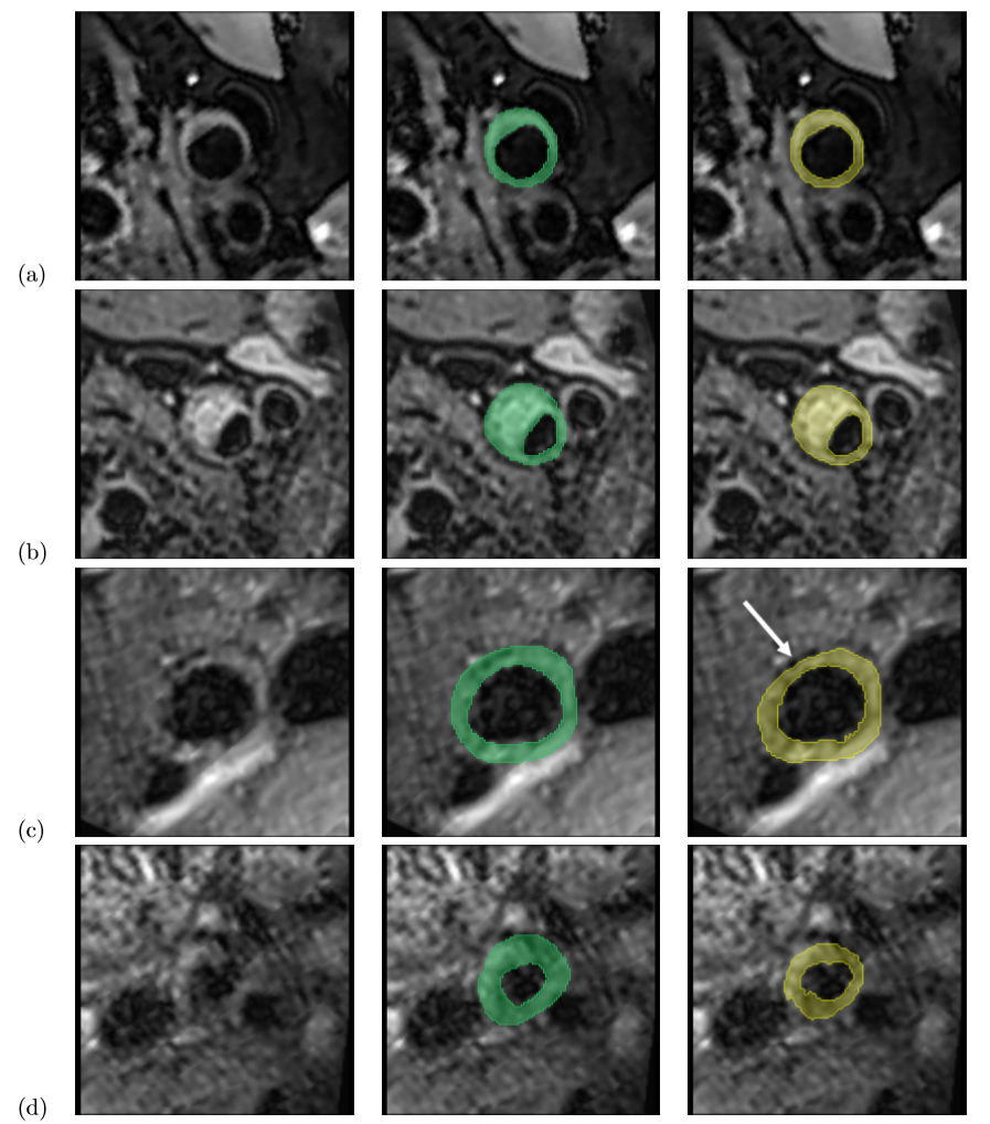
All 199 test slices were segmented using our trained network. Table 1 shows the quantitative results for the test data set. Best results were achieved for the CCA, while the lumen segmentation performed worst for stenosis cross-sections, and vessel wall detection was least reliable in the ECA in terms of the dice coefficient. The median Hausdorff distance was below the voxel size of 0.6mm for both lumen and vessel wall. Sample images are displayed in Fig. 2. For most cases, the model was able to obtain an accurate segmentation (Fig. 2(a+b)). In some cases the dice coefficient was high, but the model missed calcifications at the plaque boundary (Fig. 2(c)). In others it failed to distinguish plaque outlines at all (Fig. 2(d)), especially when the signal to noise ratio was low.Discussion & Conclusion
In our tests, the model was able to reliably segment the lumen and vessel wall in most cases. Our approach is similar to Shi et al.6, but we could noticeably improve our results by also including a distance map to the pre-computed centerline, which helped to eliminated false positives from unrelated vessels. However, the model can probably be further improved by including 3D context data as well as multiple contrasts to obtain an accurate segmentation in slices with higher signal-to-noise ratio or very inhomogeneous plaques. A major drawback of the proposed network is that an accurate vessel centerline must be known in advance. In the future we aim to use our 2D-Model to compute 3D segmentations by fitting a 3D mesh to the 2D contours, which can then be used to train a 3D network thus eliminating the need of the centerline.Acknowledgements
Grant support by the Deutsche Forschungsgemeinschaft (DFG) under grant numbers DFG HA 5399/5-1, HE7312/4-1, HE 1875/29-1 and the German Federal Ministry of Education and Research (BMBF project Berlin Center for Machine Learning (01IS18037E)) is greatly acknowledged.References
1. Zhaoyang Fan et al. “Carotid arterial wall MRI at 3T using 3D variable-flip-angle turbo spin-echo (TSE) with flow-sensitive dephasing (FSD)”. In: Journal of Magnetic Resonance Imaging 31.3 (2010), pp. 645– 654
2. Lilli Kaufhold et al. “Image-based assessment of uncertainty in quantification of carotid lumen”. In: Journal of Medical Imaging (Bellingham, Wash.) 5.3 (July 2018), p. 034003.
3. Marius Lindauer et al. “BOAH: A Tool Suite for Multi-Fidelity Bayesian Optimization & Analysis of Hyperparameters”. In: arXiv:1908.06756 [cs, stat] (Aug. 16, 2019). arXiv: 1908.06756. url: http:// arxiv.org/abs/1908.06756.
4. Petty George W. et al. “Ischemic Stroke Subtypes”. In: Stroke 30.12 (Dec. 1, 1999), pp. 2513–2516.
5. Olaf Ronneberger, Philipp Fischer, and Thomas Brox. “U-Net: Convolutional Networks for Biomedical Image Segmentation”. In: Medical Image Computing and Computer-Assisted Intervention - MICCAI 2015. Ed. by Nassir Navab et al. Lecture Notes in Computer Science. event-place: Cham. Springer International Publishing, 2015, pp. 234–241.
6. Feng Shi et al. “Intracranial Vessel Wall Segmentation Using Convolutional Neural Networks”. In: IEEE Transactions on Biomedical Engineering 66.10 (), pp. 2840–2847.
Figures