3413
Local B1-Enhanced 3D Spin-Echo Imaging for Metal Artifact Reduction1Department of Internal Medicine II, University Medical Center Ulm, Ulm, Germany, 2Department of Radiology and Neuroradiology, University Medical Center Kiel, Kiel, Germany
Synopsis
Artifacts due to the presence of metallic dental materials often limit the application of MRI. These materials, such as dental implants or fillings, often cause substantial artifacts e.g. in the oral cavity impairing diagnostic accuracy. In this contribution, we present an approach for conducting spin-echo based sequences with significantly reduced flip angles and high excitation bandwidths of up to 17 kHz by using an inductively coupled local coil, which in combination with single-point methods enables almost completely artifact-free local imaging of e.g. dental titanium implants.
Introduction
Field inhomogeneities, e.g. induced by metallic implants, cause strong off-resonances resulting in often severe image artifacts in its vicinity. Spin-echo (SE) techniques are conventionally applied to cope with the resulting rapid T2* decay1. The need for large flip angles (FA) results in a limited excitation pulse bandwidth, leading to signal voids close to a metallic object due to non-excited off-resonant spins. In order to remove these signal voids, multispectral imaging (MSI) methods like MAVRIC-SL2 have been suggested. However, MSI methods are prone to additional image artifacts, caused by the combination of the separately acquired spectral images3. In this contribution, we present a method that allows for local SE scans with drastically reduced global FAs and high excitation bandwidths, thus enabling excitation of spins even in close vicinity of metallic objects. In combination with a single-point imaging (SPI) approach4, the feasibility of nearly artifact free local imaging near metallic dental materials is demonstrated.Methods
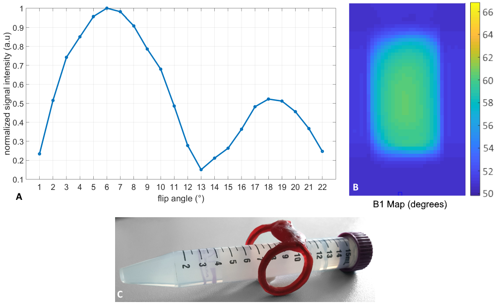
All data were acquired with a 3T whole-body clinical imaging system (Achieva, Philips Healthcare, The Netherlands) with a four-element receive coil (Carotid Coil, Shanghai Medical Technologies). An additionally used inductively coupled volume coil (ICC)5 lead to local SNR enhancement within its local sensitivity range, thereby intrinsically reducing the FOV. For the proposed approach, no decoupling of the ICC was performed during excitation, resulting in a strong local B1 and hence FA enhancement within the sensitivity region of the coil. With this approach, 90° and 180° pulses can be achieved locally with low global RF excitation power, enabling shorter pulse durations, higher excitation bandwidths and shorter acquisition times.The vendor’s 3D Turbo Spin Echo (3D-TSE) sequence was modified to allow the use of high-bandwidth Sinc-Gauss pulses (3D-hBW-TSE). In order to completely avoid distortions and pile-up artifacts a fully phase encoded 3D-TSE SPI sequence (3D-hBW-PESE) employing non-selective block-shaped excitation and refocusing pulses was implemented. In order to identify the load dependent B1 enhancement of the ICC, several FIDs, each excited with a different FA (in the range of 1°-25°), were acquired before each experiment. From the maximum and minimum signal intensities of the first data points (k0), the local 90° and 180° FA equivalents were identified. A B1 map of a phantom (agarose filled tube) was acquired for validation. All data were reconstructed with an in-house build reconstruction framework implemented in Matlab.
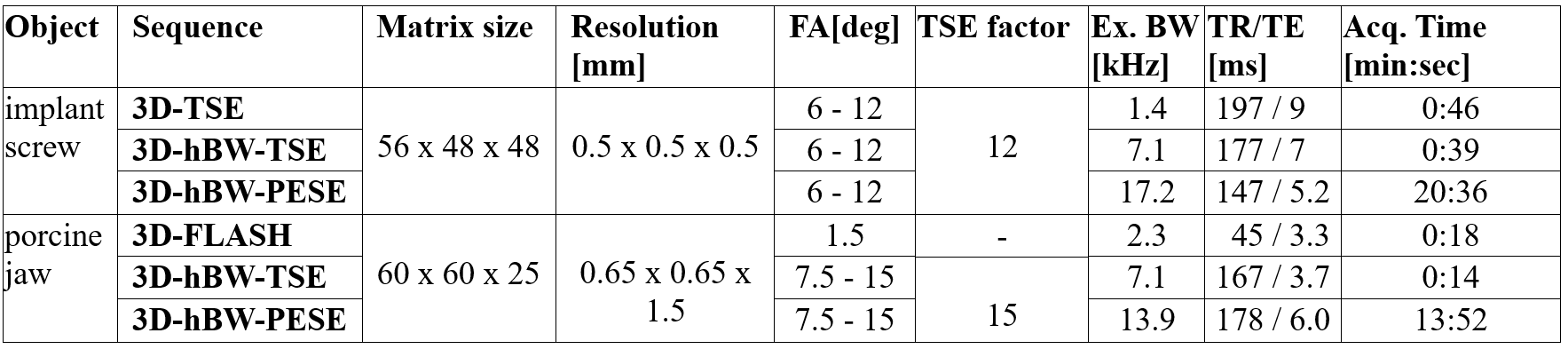
The suggested approach was evaluated for a titanium dental implant screw (10x4.1mm) immersed in agarose and a porcine jaw containing two dental implant screws. Relevant imaging parameters are provided in Table 1.
Results
Fig. 1A shows the FID signal intensities in dependence on the global FA applied. A global FA of 6° was identified as the 90° equivalent, indicating a 15-fold FA enhancement in the sensitivity range of the ICC. The respective B1 map (Fig. 1B) acquired with global FA of 4° revealed a local ICC FA of 60°, thus confirming the 15-fold FA enhancement.FA pairs of 6°-12° (agarose phantom) and 7.5°-15° (porcine jaw) yielded maximum excitation and refocusing bandwidths of 7.1 kHz (phantom and jaw) for the 3D-hBW-TSE and 17.2 kHz (phantom) / 13.9 kHz (jaw) for the 3D-hBW-PESE sequences. In comparison, for conventional 3D-TSE the maximum excitation bandwidth for a 90°-180° pulse pair resulted in 1.4 kHz.
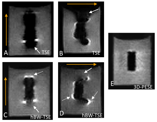
Fig. 2 shows the 3D-TSE (A,B), 3D-hBW-TSE (C,D) and 3D-hBW-PESE (E) images of the implant screw for two different frequency encoding directions. Signal loss and distortions are clearly visible in the 3D-TSE images, which can be clearly reduced in the 3D-hBW-TSE images. The slightly increased pile-up artifacts as well as the remaining image distortions can almost completely be removed with 3D-hBW-PESE. Quantitative analysis of the apparent screw dimension yields 22.3x8.7 mm² (3D-TSE), 14.7x6.2 mm² (3D-hBW-TSE), and 10.4x4.5mm² (3D-hBW-PESE).
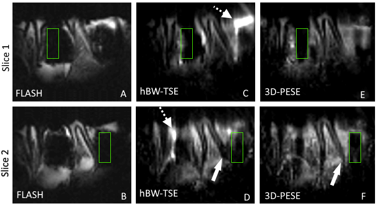
Images of a porcine jaw containing two titanium dental bone-level implant screw (Fig. 3) show similar outcome. The large areas with signal loss resulting in the FLASH images (A,B) can be reduced with the 3D-hBW-TSE approach (C,D). 3D-hBW-PESE (E,F) results to almost complete removal of all apparent susceptibility induced artifacts.
Discussion and Conclusions
Typical metal-induced artifacts as visible in conventional 3D-TSE and 3D-FLASH techniques can be distinctly reduced by higher excitation bandwidth 3D-hBW-TSE, enabled by local B1 enhancement. However, the increase in excitation bandwidth can lead to stronger pile-up artifacts in sequences using frequency encoding, due to the larger amount of off-resonant excited spins. Almost completely artifact free images can be achieved by combining local B1 enhancement with spin echo based SPI techniques as shown by the 3D-hBW-PESE approach. Even though the combination of local B1 enhancement with conventional 3D-TSE methods yield distinct metal artifact reduction, in cases where the direct vicinity of e.g. the implant is of interest the combination with SPI methods appears promising. Further combination of 3D-hBW-PESE with advanced undersampling techniques6 may further foster clinical application by acquisition times in the minute range.Acknowledgements
JBH wishes to acknowledge funding by the DFG (HO-4604/2-1)
The authors thank the Ulm University Center for Translational Imaging MoMAN for its support.
References
[1] Jungmann P M, Agten C A, Pfirrmann C W, et al. Advances in MRI Around Metal. Journal of Magnetic Resonance. 2017;46:972–991.
[2] Koch, K M, Brau, A C, Chen W, et al. Imaging near metal with a MAVRIC-SEMAC hybrid. Magn Reson Med 2011;65:71-82.
[3] Quist B, Shi X, Weber H, et al. Improved Field-Mapping and Artifact Correction in Multispectral Imaging. Magn Reson Med. 2017;78(5):2022-2034.
[4] van Gorp J S, Bakker C J G, Bouwman J G, et al. Geometrically undistorted MRI in the presence of field inhomogeneities using compressed sensing accelerated broadband 3D phase encoded turbo spin-echo imaging. Phys. Med. Biol. 2015;60:615–631
[5] Ludwig U, Eisenbeiss A K , and Scheifele C., et al. Dental MRI using wireless intraoral coils. J. Scientific Reports. 2016;6:23301.
[6] Speidel T, Paul J, Wundrak S., et al. Quasi-Random Single-Point Imaging Using Low-Discrepancy k -Space Sampling. IEEE Trans Med Imaging. 2018;37(2):473-479.
Figures