3404
Reverse-Encoding MRI Near Metallic Implants Using Missing Pulse Steady-State Free Precession1Center for Magnetic Resonance Research, Department of Radiology, University of Minnesota, Minneapolis, MN, United States
Synopsis
Clinical MRI sequences for imaging near metallic implants are mainly multi-spectral approaches, with fast spin-echo acquisitions to achieve clinically relevant scan times. Due to the large bandwidths necessary for refocusing all off-resonance spins near metallic implants, usually the refocusing pulse flip angles must be limited to a sub-optimal value to permit a safe specific absorption rate. Here, a low peak amplitude, radiofrequency refocused sequence is used to limit energy deposition. Reversed encoding is employed, where two acquisitions are collected with opposite frequency-encoding gradient polarity. An estimate of the displacement field is found using a B-spline basis and the magnitude images.
Purpose
A small number of sequences are currently available for MR imaging near metallic implants in a clinically relevant scan time [1]–[3] due to the large induced field inhomogeneities. While the methods in [1]–[3] rely on multispectral imaging (MSI) approaches, Chang & Fitzpatrick [4] previously proposed a self-consistency approach for correcting image distortions by acquiring two images with opposite frequency-encoding gradient polarity, hereafter referred to as reverse-encoding. More recently, Skare & Andersson [5] demonstrated reverse-encoding near an aneurysm clip. Therein, the excitation bandwidth was low (860 Hz) with a fixed frequency, artificially reducing field inhomogeneity by imaging only a narrow band of frequencies. Here, high-bandwidth (20 kHz) excitation pulses are used, and an estimate of the displacement field is generated similarly to that in [5].Methods
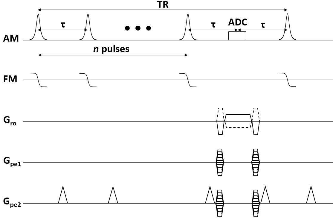
The Missing Pulse Steady-State Free Precession (MP-SSFP) [6] sequence was used, whereby a train of n small-flip angle pulses are applied to achieve a steady-state. Data are acquired in place of the n+1 pulse, where an echo forms. This sequence achieves radiofrequency (RF) refocusing with low peak amplitude. The reverse-encoding was implemented such that acquisition of the same phase encoding line for each gradient polarity was separated by a single TR (Figure 1) to limit motion artifacts. The displacement field was estimated by aligning the intensity-corrected, resampled magnitude images resulting from the opposing gradient polarities, parameterizing the displacement in terms of 3D B-splines [5].Phantom experiments were performed with a Varian DirectDrive console (Agilent Technologies, Santa Clara, CA) interfaced to a 1.5T, 90-cm magnet (Oxford Magnet Technology, Oxfordshire, UK) with a clinical gradient system (model SC72, Siemens, Erlangen, Germany). The magnet was designed for use at 4T but, to achieve a more clinically relevant field, has been ramped to 1.5T for these experiments. The phantom consisted of agar with one stainless steel and one titanium screw embedded inside. A quadrature transverse electromagnetic (TEM) RF coil (Virtumed, Minneapolis, USA) was used for transmit and receive.
The MP-SSFP sequence used n = 3 pulses, TR = 25.86 ms, and 250 kHz receiver bandwidth. Hyperbolic secant [7] pulses were used, with time-bandwidth product 10, 500 µs duration, 20 kHz bandwidth, and 10˚ flip angle. The field-of-view (FOV) was 256x256x256 mm3 with 2 mm resolution, and total scan time of 14.12 minutes. The reconstruction used 3 mm spline knot spacing to estimate the displacement field, totaling 614,125 parameters to estimate. In [5], an estimate of the Hessian is evaluated at each update in part to account for the difference in magnitude of displacement and motion parameters. Here, a first-order method, namely conjugate gradient, sufficed as motion artifacts were mitigated in the sequence.
For comparison, the multi-acquisition variable-resonance image combination (MAVRIC) sequence was implemented [1], and the different off-resonance images were corrected prior to root-sum-of-squares combination to limit blurring [2]. Twenty frequency bins were separated by 1 kHz with 2.25 kHz bandwidth, using approximately box-car excitation, 135° Gaussian refocusing, and TR = 3.07 s. One phase encoded dimension was split into 8 segments, each with echo-train length 16. Identical resolution, FOV, and receiver bandwidth was used as in the MP-SSFP technique, with 52 minutes total scan time. As MP-SSFP was both faster and had visibly lower signal-to-noise ratio (SNR), another scan was performed with 4 averages to achieve a similar total scan time (56 minutes) to MAVRIC. A conventional 3D fast spin-echo (FSE) was acquired for comparison.
Results
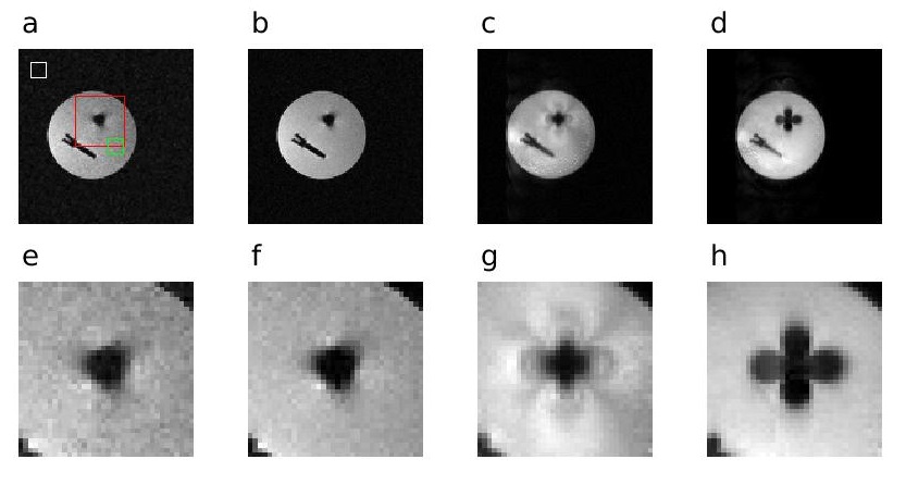
A side-by-side comparison of a selected cross section from each acquisition (MP-SSFP, MAVRIC and conventional FSE) is presented in Figure 2. Both MP-SSFP and MAVRIC outperform FSE by retaining more signal closer to the screws, despite large off-resonances. However, MP-SSFP does not suffer from the ripple effect near the metal, as is the well-known case with MAVRIC [8].The SNR of MP-SSFP with one and four averages was 31.31 and 57.23, respectively, while the MAVRIC SNR was 130.97, as determined from a region-of-interest analysis (ROI) – see Figure 2.
Discussion
The primary disadvantage of the MP-SSFP technique described here is the absence of slab selection, which would permit a shorter scan time. While slab selection is possible, phase encoding remains necessary in the spatially-selected dimension [2], [3] to resolve slab distortions. On the other hand, the short TR of MP-SSFP alleviates the need for spatial selection.Previous work [8], [9] has used reverse-encoding to correct images near metallic implants, although MSI techniques were used in those works. Here, it was demonstrated that reverse-encoding with broadband RF refocusing performs well near metallic implants without resorting to MSI methods.
Future work will focus on achieving higher spatial resolution within a fixed scan time. Additional emphasis will be placed on complex image combination from the opposite polarity acquisitions to improve SNR over magnitude image combination. This remains a challenge due to phase differences between the two acquisitions.
Acknowledgements
This work was supported by the National Institutes of Health grants U01 EB025153 and P41 EB015894. The authors would like to thank Dr. Casey Johnson for providing the screws to embed in the phantom.References
[1] K. M. Koch, J. E. Lorbiecki, R. S. Hinks, and K. F. King, “A multispectral three-dimensional acquisition technique for imaging near metal implants,” Magn. Reson. Med., vol. 61, no. 2, pp. 381–390, 2009.
[2] K. M. Koch et al., “Imaging near metal with a MAVRIC-SEMAC hybrid,” Magn. Reson. Med., vol. 65, no. 1, pp. 71–82, 2011.
[3] W. Lu, K. B. Pauly, G. E. Gold, J. M. Pauly, and B. A. Hargreaves, “SEMAC: Slice encoding for metal artifact correction in MRI,” Magn. Reson. Med., vol. 62, no. 1, pp. 66–76, 2009.
[4] H. Chang and J. Fitzpatrick, “A Technique for Accurate Magnetic Resonance Imaging in the Presence of Field Inhomogeneities,” Ieee Tmi, vol. 11, no. 3, pp. 319–329, 1992.
[5] S. Skare and J. L. R. Andersson, “Correction of MR image distortions induced by metallic objects using a 3D cubic B-spline basis set: Application to stereotactic surgical planning,” Magn. Reson. Med., vol. 54, no. 1, pp. 169–181, 2005.
[6] S. Patz, S. T. S. Wong, and M. S. Roos, “Missing pulse steady‐state free precession,” Magn. Reson. Med., vol. 10, no. 2, pp. 194–209, 1989.
[7] M. . Silver, R. . Joseph, and D. . Hoult, “Highly selective and π pulse generation,” J. Magn. Reson., vol. 59, no. 2, pp. 347–351, 1984.
[8] X. Shi, B. Quist, and B. Hargreaves, “Pile‐up and ripple artifact correction near metallic implants by alternating gradients.,” in Proceedings of the 25th Annual Meeting of ISMRM, Honolulu, Hawaii, 2017, p. 574.
[9] K. Kwon, D. Kim, B. Kim, and H. Park, “Unsupervised learning of a deep neural network for metal artifact correction using dual‐polarity readout gradients,” Magn. Reson. Med., vol. 83, no. 1, pp. 124–138, 2020.
Figures