3401
Optimal Coil Combination with Relatively Aligned Phase (RAP) for Phase-Cycled bSSFP Imaging1Radiology, University of British Columbia, Vancouver, BC, Canada, 2Radiology, University of Washington, Seattle, WA, United States
Synopsis
Phase-Cycled (PC) bSSFP imaging is useful for qualitative and quantitative studies of tissue. But the images generated should be properly combined when they are acquired with multiple receiver coils; in particular, phase information in the complex images must be preserved. We describe a straightforward yet optimal coil combination algorithm for PC-bSSFP applications, where the phase is preserved through relative phase alignment along the measurement dimension. The method is demonstrated with experimental results from phantom and volunteer scans.
Introduction
Owing to its high efficiency and exceptional image quality, balanced steady state free precession (bSSFP) imaging has a broad range of applications. Diagnostic utility is further improved with phase-cycling, where an elliptical signal model1 allows complete removal of troublesome banding artifacts and quantitative evaluation of physical parameters2. When multiple receiver coils3 are used, images from all N coils must be combined to form a composite image. One option is to perform bSSFP processing for each individual coil, and then combine the N results after. A second option is to combine the raw images first, followed by bSSFP processing of the composite image. The latter approach not only has higher time efficiency, but also avoids processing low signal pixels to achieve optimized results.Existing methods for coil combination include: the sum of squares (rSOS)3, which is simple, effective, and yields high SNR and desirable image uniformity, but unfortunately does not preserve phase information; the adaptive reconstruction (AR)4, which uses sophisticated calculations to find coil weightings via eigenvectors for optimal SNR, but may not be simultaneously optimal for all phase cycles in bSSFP; the virtual reference coil (VRC)5, which requires a shared sensitivity among all coils to avoid an undesirable "daisy-chain" complication; and the reference scan (RS)6, which requires additional data that is not always practical to acquire.
In this work, a straightforward yet optimal algorithm for coil combination is introduced. It first leverages information across different phase cycles, or along the measurement dimension, to achieve a phase alignment of all coils. Coil-by-coil magnitude data is then combined with rSOS3 and phase data with optimal-weighted-averaging (OWA)7,8. Experimental results from phantom and volunteer scans are presented.
Method
Complex bSSFP images with (0°,90°,180°,270°) phase-cycling were acquired on a 3T scanner (Phillips Ingenia, Eindhoven, the Netherlands). A coil array with N=13 channels was used to scan a phantom containing a metal implant, with FA/TE/TR= 40°/2.3ms/4.7ms. Images were also acquired from a volunteer with a metal hip implant using a 25-channel receiver coil, with FA/TE/TR=30°/2.5ms/5.0ms.Images were processed with the following steps.
(1) For each channel, all four phase-cycled complex images were averaged, resulting in N mean complex images <CS>. These N images were used as phase references for phase alignment.
(2) Each channel’s <CS> phase was removed from each of the channel’s phase cycles; this was repeated for all N coil channels. Each phase cycle then had similar phase but spatially varied noise over all channels, achieving phase alignment.
(3) For each phase cycle, coil magnitude was combined using rSOS3 for high SNR and uniform signal across the field-of-view, and coil phase was combined using OWA7,8 , which employs normalized weightings that are inversely proportional to the local noise variance in each channel. To avoid phase wrap complications, the noise variance was estimated from the corresponding complex phasors9.
(4) The resulting four composite phase-cycled complex images were processed with the Geometric Solution (GS)1 to achieve banding artifact removal.
Results
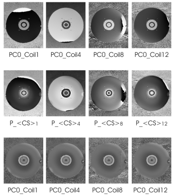
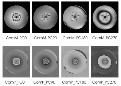
Figure 1 shows intermediate phase images from four representative coils (coil #1, #4, #8, and #12). The top row depicts original, unaligned phase maps for the 0° phase cycle; the middle row shows the <CS> phase maps to be removed from all four phase cycles for each channel to achieve phase alignment; the bottom row shows phase maps for the 0° phase cycle after phase alignment. The bottom-row phase appears aligned across coil channels as compared to the top row phase.Figure 2 shows all phase-cycled magnitude and phase images after coil combination, with spatially shifted dark bands.
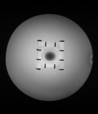
Figure 3 shows the final GS de-banded magnitude image, with all dark bands effectively removed.
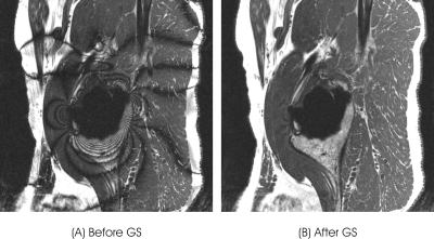
Figure 4 shows in vivo results from a volunteer with a metal hip implant, (A) before and (B) after de-banding by GS.
Discussion
For bSSFP imaging, it is the relative phase, rather than the absolute phase, that is important. Therefore, the mean image <CS> can be used as a phase reference for relative phase alignment. Such a phase alignment is equivalent to a global rotation of the signal ellipse1, without changing its basic properties. In fact, any of the four phase-cycled images can also be chosen as phase reference, although the mean image <CS> is preferred for higher SNR. The same concept has been used for other phase-sensitive coil combinations that use multiple measurements10,11. The proposed method offers an ideal result using moderate processing by taking advantage of intrinsic phase information along the measurement dimension.Conclusion
A method with relatively aligned phase (RAP) for optimal coil combination is introduced. It is demonstrated experimentally by phantom and volunteer scans for bSSFP imaging.Acknowledgements
No acknowledgement found.References
[1] Xiang QS, Hoff MN. Banding artifact removal for bSSFP imaging with an elliptical signal model. Magn Reson Med. 2014;71:927–933.
[2] Shcherbakova Y, van den Berg CAT, Moonen CTW, et al, PLANET: An Ellipse Fitting Approach for Simultaneous T1 and T2 Mapping Using Phase-Cycled Balanced Steady-State Free Precession, Magn Reson Med. 2018;79:711–722.
[3] Roemer PB, Edelstein WA, Hayes CE, et al. The NMR phased array. Magn Reson Med. 1990;16:192–225.
[4] Walsh DO, Gmitro AF, Marcellin MW. Adaptive reconstruction of phased array MR imagery. Magn Reson Med. 2000;43:682–690.
[5] Parker DL, Payne A, Todd N, et al. Phase reconstruction from multiple coil data using a virtual reference coil. Magn Reson Med. 2014;72:563–569.
[6] Robinson SD, Dymerska B, Bogner W, et al. Combining phase images from array coils using a short echo time reference scan (COMPOSER). Magn Reson Med. 2017;77:318–327.
[7] Zhang J, Bjornson B, Xiang QS. Combining multi-channel MP2RAGE images with minimized noise, In Proceedings of the 24th ISMRM, Singapore, 2016. Abstract 1917.
[8] Hoff MN, Andre JB, Xiang QS. Combined Geometric and Algebraic Solutions for Removal of bSSFP Banding Artifacts with Performance Comparisons, Magn Reson Med. 2017;77:644–654.
[9] Immerkær J, Fast Noise Variance Estimation, Computer Vision and Image Understanding. 1996; 64(2): 300–302.
[10] Chavez S, Ramsay E, Haider E, et al. Distortion correction of multi-coil diffusion-weighted EPI using the phase-based method: PLACE, In Proceedings of the 19th ISMRM, Montreal, Canada, 2011. Abstract 4573.
[11] Xiang QS. Two-point water-fat imaging with partially-opposed-phase (POP) acquisition: an asymmetric Dixon method. Magn Reson Med. 2006;56:572–584.
Figures


