3395
Feasibility of Monitoring Geometric Distortion for Radiation Therapy Planning using ACR Weekly QA
Chen Lin1, Stephanie Tensfeldt1, and Christopher Serago2
1Radiology, Mayo Clinic, Jacksonville, FL, United States, 2Radiation Oncology, Mayo Clinic, Jacksonville, FL, United States
1Radiology, Mayo Clinic, Jacksonville, FL, United States, 2Radiation Oncology, Mayo Clinic, Jacksonville, FL, United States
Synopsis
To demonstrate the distortion measurements based on automatic analysis of American College of Radiology (ACR) weekly quality assurance (QA) scans is adequate for monitoring the geometric distortion of a MR scanner for radiation therapy planning by comparing with distortion measurements using a 3D grid phantom.
INTRODUCTION
Monitoring geometric distortion in MRI images used for radiation therapy planning and other stereo-tactic procedures is critical in order to ensure the accuracy of treatment delivery. Such quality assurance is typically done by scanning a 3D grid phantom and analyzing the spatial displacement of control points from their known positions1. However, adding a dedicated and time consuming geometric distortion QA procedure to the routine QA is challenging, especially for a large fleet of MR scanners. On the other hand, ACR weekly QA (ACR QA) is already being performed for MR scanners accredited by ACR2. If the basic geometric distortion measurement based on ACR QA is sensitive and correlated with the more comprehensive geometric distortion based on a 3D grid phantom3, it may serve a surrogate to monitor the distortion and ensure that it is within the appropriate limits for radiation therapy.METHODS
To test such hypothesis, distortion measurements were performed on a Siemens 3T Vida scanner. Increasing amount of geometric distortion from gradient calibration errors was simulated by systematically changing the B0 shim in X and Y directions from the initial optimized shim setting. For each shim setting, geometric distortion was quantified based on ACR QA and using QUASAR™ GRID3D image distortion analysis system by Modus QA (GRID3D QA). ACR QA were performed according to the protocol and imaging parameters specified by ACR for weekly QA using a Siemens 20ch head&neck coil with receiver bandwidth (rBW) of 150 Hz/px. The acquired ACR phantom images were analyzed automatically using an in-house analysis software to measure the phantom length in Z and diameters in X and Y . For GRID3D QA, a 3D fast gradient echo sequence was used to acquire images of 1.0 mm isotropic resolution with rBW of 170Hz/pixel. The 3D datasets were analyzed using Modus GRID3D software to provide a full 3D distortion map and calculate mean displacement, maximum displacement and percentage of control points with displacement > 1.5mm in X, Y and Z directions as well as for the combined displacement vector.RESULTS
Figure 1 shows typical axial images of the ACR phantom and Modus GRID3D phantom. Automatic analysis of ACR phantom was successful for all measurements. Likewise, GRID3D analysis was also successful with 100% of control points found in each case. Figures 2 – 4 show the measured absolute deviation of ACR phantom diameter in X direction (ACR Dx) of up to 6 mm with the change of shim settings. Also in the plots is the measured X displacement statistics for the same shim setting. The range of change of mean displacement in X direction (GRID3D Dx[Mean]), maximum displacement in X direction (GRID3D Dx[Max]) and percentage of control points with displacement > 1.5mm in X direction (GRID3D Dx[%>1.5mm]) were 3.0mm, 0.8mm and 14%. Little change in Y diameter of ACR QA and Y displacement in GRID3D QA was observed (not shown). There are strong correlations between the GRID3D displacement statistics and deviation of ACR phantom diameter with correlation coefficients of 0.915, 0.847 and 0.787 between GRID3D Dx[Mean], GRID3D Dx[Max], GRID3D Dx[%>1.5mm] and ACR Dx. For the first five shim settings where the change of shim currents is between 0 and 40 a.u. and the distortion was relatively small, ACR Dx showed a gradual increase from 0.0 mm to 2.0 mm while relatively little change was observed in all three GRID3D displacement statistics. With the further increase of shim current, ACR Dx continued to increase and displacement statistics started to change as well. Such behavior suggests that the change of ACR phantom diameter is more sensitive to small distortion than GRID3D displacement statistics.DISCUSSION
Since the deviation of ACR phantom diameter is correlated with the displacement statistics measured from a 3D grid phantom and has high sensitivity to minor distortion, it’s a good indicator of overall distortion and can be easily and objectively measured if there is an automatic analysis program. However, given the size of ACR phantom, it may only be used to monitor the distortion within similar FOV.Although the same amount shim current change was introduced in Y direction, it’s surprising that distortion in Y did not change and remained small. It could be that the amount of gradient in Y was not as large with same amount of current. But further investigation is needed to confirm.
Future validation will include experiments to demonstrate the correlation between ACR QA and GRID3D QA when there is substantial amount of distortion in all three directions. Currently, a 1.0mm action criterion for the deviation of ACR phantom length and diameters is used to monitor geometric distortion in a fleet of 10 MR scanners. The effectiveness of such distortion QA program is being evaluated by comparing with GRID3D QA quarterly.
CONCLUSION
Limiting the ACR phantom diameter deviation to 1.0 mm would limit the mean displacement within 0.5 mm, maximum displacement within 2.0 mm and percentage of control points with displacement > 1.5 mm less than 1% in 3D grid phantom in the same direction.Acknowledgements
References
- Torfeh T et al. Characterization of 3D geometric distortion of magnetic resonance imaging scanners commissioned for radiation therapy planning, Magn Reson Imaging. 2016 Jun;34(5):645-53
- 2015 ACR MRI Quality Control Manual
- Stanescu T. et al. Investigation of a 3D system distortion correction method for MR images, Journal of Applied Clinical Medical Physics, Vol. 11, No. 1, Winter 2010, pp 200-21
Figures
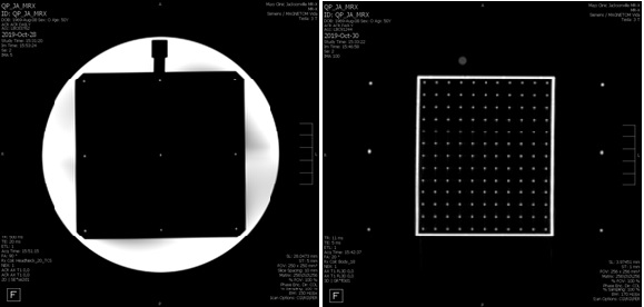
Axial image of ACR phantom and
ModusQA GRID3D phantom. The ACR phantom is cylindrical with a diameter of 190
mm and a length of 148 mm. The ModusQA GRID3D phantom is cubical with dimensions
of 140 mm x 130 mm x 110 mm. It has 2002 control points.
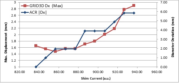
Deviation of measured ACR phantom diameter in
X-axis (ACR |Dx|) versus the maximum displacement in X-axis in GRID 3D phantom
(GRID3D Dx [Max.]) under different shim settings.
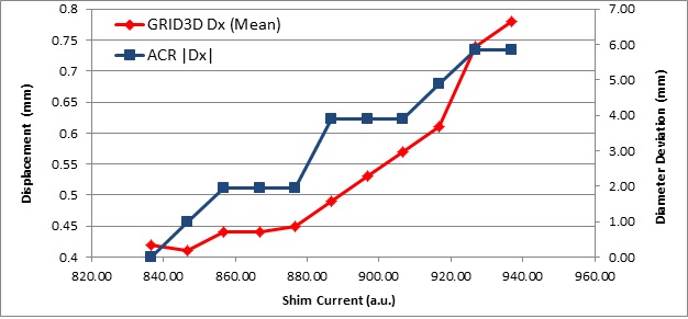
Deviation of measured ACR
phantom diameter in X-axis (ACR |Dx|) versus the mean displacement in X-axis in
GRID 3D phantom (GRID3D Dx [Mean]) under different shim settings.
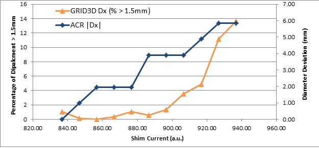
Deviation of measured ACR phantom diameter in
X-axis (ACR |Dx|) versus percentage of control points in GRID 3D phantom with
displacement in X-axis greater than 1.5mm (GRID3D Dx % > 1.5 mm) under different shim settings.