3393
Correcting Gradient Delays in Multi-Echo Rosette Trajectories with RING1EECS, UC Berkeley, Berkeley, CA, United States, 2Radiology, Stanford, Stanford, CA, United States
Synopsis
Rosette trajectories are sensitive to gradient delays as caused by eddy currents. Here, we use the RING method recently proposed for radial trajectories to correct for these delays. To this end, we approximate the center portion of the Rosette trajectory to be radial-like, determine delay constants, and correct the entire trajectory in a second step. First phantom and patient studies show that this simple correction method improves image quality in multi-echo Rosette imaging and leads to prolonged T2* values in derived maps. The small amount of required data renders echo-adaptive corrections feasible.
INTRODUCTION
Gradient delays caused by eddy currents are a common problem in modern MRI systems. These delays lead to deviations from the intended sampling trajectory and degrade image quality, especially in non-Cartesian sequences. Therefore, a variety of compensation methods have been developed, some requiring specialized hardware1 and/or separate calibration measurements2, others are auto-calibrated but computational intense3,4. For radial imaging, Rosenzweig and coworkers recently introduced RING5, a robust auto-calibration method that requires only a few data points. In this work, we demonstrate that RING can also be used to correct trajectory errors in Rosette trajectories [Figure 1].THEORY
RING models trajectory errors $$$ \delta \textbf{k}_{\theta} $$$ caused by gradient delays in radial trajectories as$$ \delta\textbf{k}_{\theta}=\left({\displaystyle \begin{matrix} S_{x} & S_{xy} \\ S_{xy} & S_{y}\\ \end{matrix}}\right)\left(\begin{array}{ll} \cos \theta\\ \sin \theta\\ \end{array}\right) $$
where $$$\theta$$$ is the projection angle, and the constants $$$S_{x}, S_{y}, S_{xy}$$$ capture the delays in the logical coordinate system caused by independent delays in each of the three physical gradients. These constants are estimated by detecting intersection points of near-orthogonal projections and solving a system of linear equations.
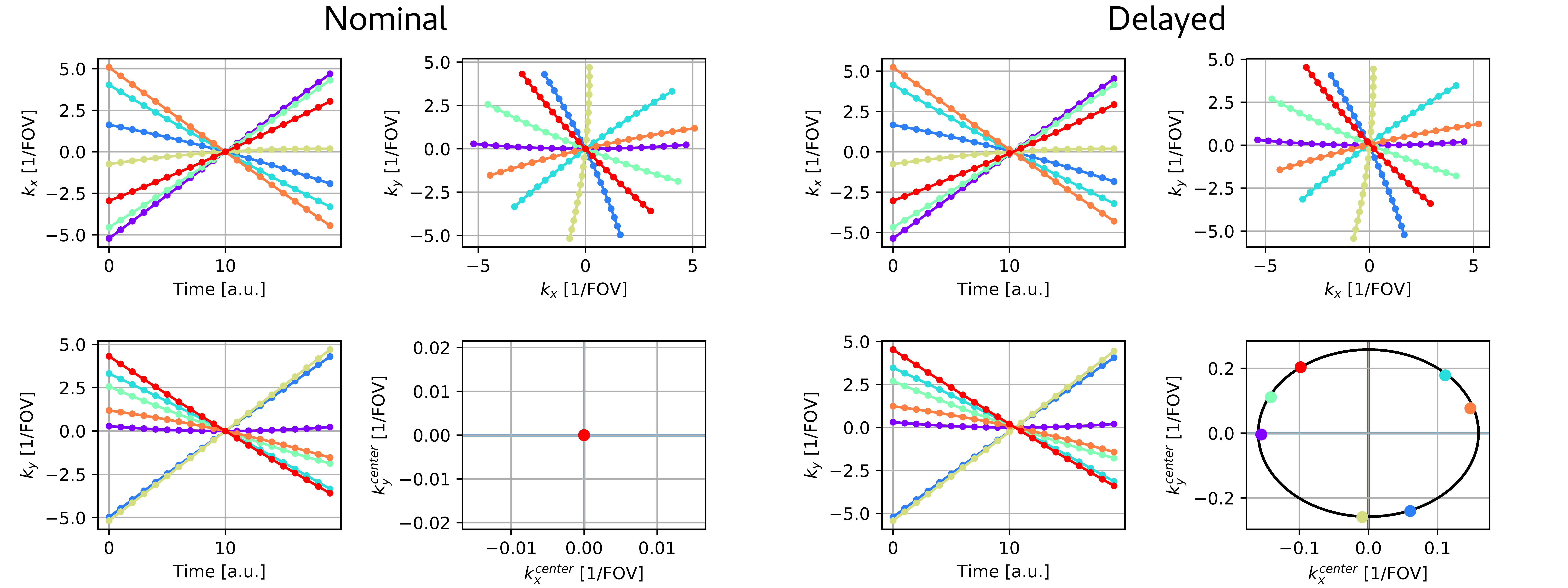
To apply this idea to Rosette trajectories6, we note that rotating Rosettes from TR to TR results in a sampling pattern in the vicinity of the k-space center that closely approximates a radial trajectory [Figure 2]. Time-consistent calibration data for RING can be obtained from multiple TRs by restricting the analysis to a specific echo time and to a small region around the k-space center. The delay constants determined from this region are then used in a second step to correct the entire trajectory7 according to
$$ \delta\textbf{k}_t=\gamma/\tau\left({\displaystyle \begin{matrix} S_{x} & S_{xy} \\ S_{xy} & S_{y}\\ \end{matrix}}\right)\textbf{G}_t $$
with gradient amplitude $$$G_t$$$ at time point $$$ t $$$, the gyromagnetic ratio $$$ \gamma $$$, and the dwell time $$$ \tau $$$.
METHODS
Imaging was performed on a 3.0T GE Signa 750 MRI system using a spoiled, multi-echo gradient-echo Rosette pulse sequence with FA = 15°, TR =17 ms, TR = 17 ms and ω2 / ω1 = 2.2. Rotating by the golden angle, 137.5°, 800 TRs were acquired resulting in a total scan time of 15 s. Gradient delays were determined from the initial 21 TRs using the 20 innermost sampling points of the first center crossing at TE = 4.7 ms and corrections then applied to the entire trajectory. Ferumoxytol-doped vials were used to create generate a phantom with T2* contrast. Five echo images were reconstructed using the BART toolbox8, with and without prior gradient delay correction. A sampling window of 800 samples per segment was used and T2* values were derived by magnitude-based mono-exponential fitting.RESULTS
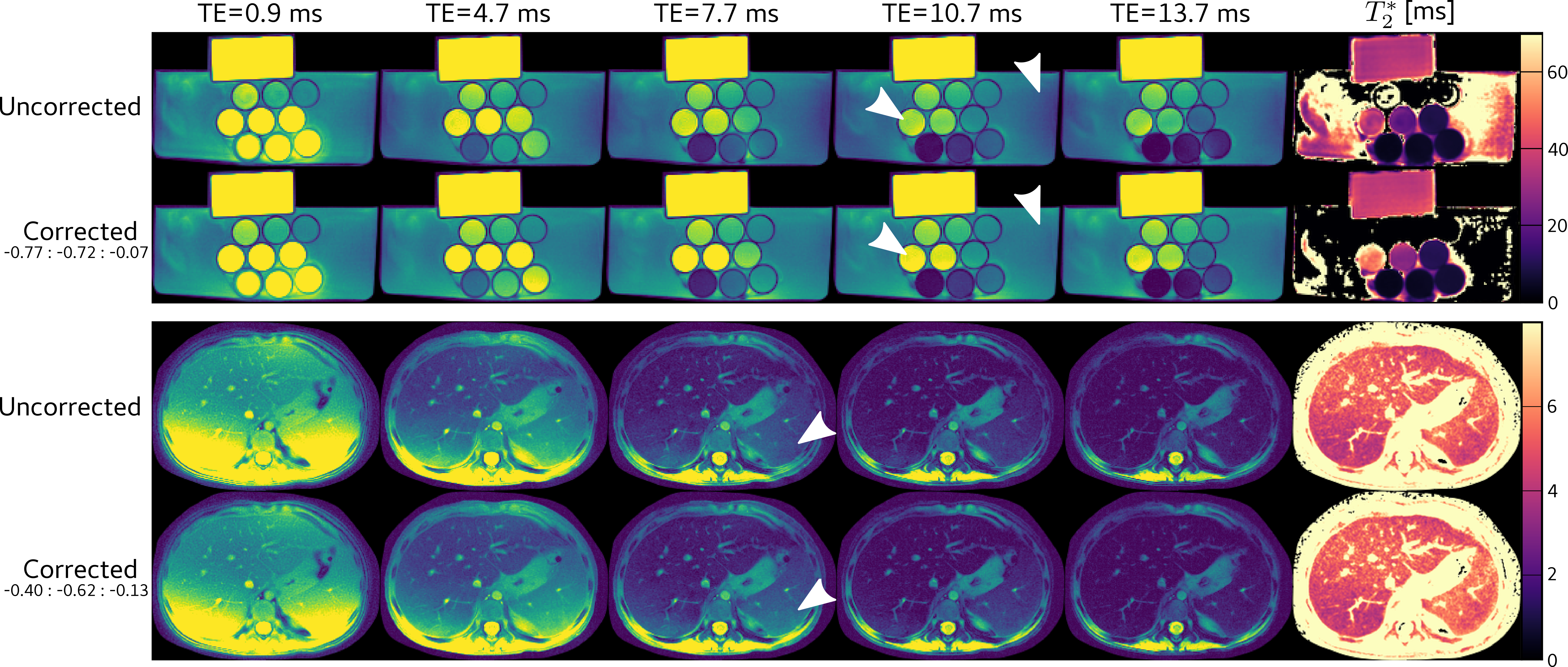
Figure 3 shows the reconstructed echo images for a phantom (top) and a patient patient undergoing clinical abdominal exam (bottom). In both cases, the applied gradient delay correction resulted in locally higher signal intensities (see arrows) and led to prolonged T2* values in the respective maps. A ROI-based quantitative analysis revealed changes of up to 53±7% for the longest T2* compartment in the phantom and 10±1% in the spleen.DISCUSSION & CONCLUSION
The presented results indicate that the RING method is suitable to correct gradient delays in Rosette trajectories and to improve accuracy in T2* mapping. The small amount of required data makes it possible to correct delays dynamically and for each echo time individually. However, the direct application of this method has two main limitations: First, approximation errors are expected to increase when Rosette sequences with smaller base resolutions are used as the curvature around k-space center increases. Second, depending on the actual implementation, the DC sample of each Rosette segment might be shifted from the center by a small offset which is not modeled by RING. A more complex model could overcome both limitations but would somewhat compromise the simplicity of the RING method.Acknowledgements
No acknowledgement found.References
1. Barmet C, Zanche ND, Pruessmann KP. Spatiotemporal magnetic field monitoring for mr. MRM 2008;60:187–197.
2. Liu H, Matson G. Accurate measurement of magnetic resonance imaging gradient characteristics. Materials 2014;7:1–15.
3. Ianni JD, Grissom WA. Trajectory auto-corrected image reconstruction. MRM 2016;76:757–768.
4. Jiang W, Larson PEZ. Simultaneous auto-calibration and gradient delays estimation ( SAGE ) in non-Cartesian parallel MRI using low-rank constraints. MRM 2018:2006–2016. doi: 10.1002/mrm.27168.
5. Rosenzweig S, Holme HCM, Uecker M. Simple auto-calibrated gradient delay estimation from few spokes using Radial Intersections (RING). MRM 2019;81:1898–1906. doi: 10.1002/mrm.27506.
6. Noll DC. Multishot rosette trajectories for spectrally selective MR imaging. IEEE transactions on medical imaging 1997;16:372–377. doi: 10.1109/42.611345.
7. Robison RK, Devaraj A, Pipe JG. Fast, simple gradient delay estimation for spiral MRI. MRM 2010;63:1683–1690. doi: 10.1002/mrm.22327.
8. Uecker M, Tamir J, Ong F, Holme C, Lustig M. Bart: Version 0.5.00, 2019. doi: 110.5281/zenodo.337674.
Figures