3389
Replaceable field probe holder for the Nova coil on a 7 Tesla Siemens scanner1MR Physics, German Center for Neurodegenerative Diseases (DZNE), Bonn, Germany, 2Skope Magnetic Resonance Technologies Inc., Zurich, Switzerland, 3Department of Physics and Astronomy, University of Bonn, Bonn, Germany
Synopsis
An optimized holder for fast mounting of the Skope clip-on field camera into the common Nova Tx/Rx head coil on a 7 Tesla Siemens scanner is presented. Field probe positioning was based on transceiver coil architecture constraints and conditioning for best approximation of field dynamics. The conditioning results for the proposed probe holder positions show very good agreement with the corresponding simulation. They approximate the optimal spherical probe arrangement as well as possible. In comparison, the probe holder outperforms the manual mounting situation conditioning-wise, which corresponds to arbitrary placement onto the receive part of the head coil.
Introduction
Within recent years, field monitoring systems based on NMR probes (1) are used increasingly to correct for hardware and physiology induced field fluctuations (2), especially at ultrahigh magnetic fields. For 7 Tesla in-vivo imaging, these setups are on the one hand described as ‘integrated’ systems, where the NMR probes are incorporated as a fixed part of the whole transmit/receive (Tx/Rx) coil setup (3,4). On the other hand, such a field monitoring system can be applied as a lose set of NMR probes that can be attached to a widely used transceiver, like the conventional 1Tx/32Rx Nova head coil. Such a temporary fixation/taping onto the receive part of the coil (5,6) applies to most field probe sites. However, it lacks the reproducibility and optimal probe placement for consecutive scan sessions. Therefore, it is desirable to develop an easily replaceable frame for optional integration of the field probe system.Methods
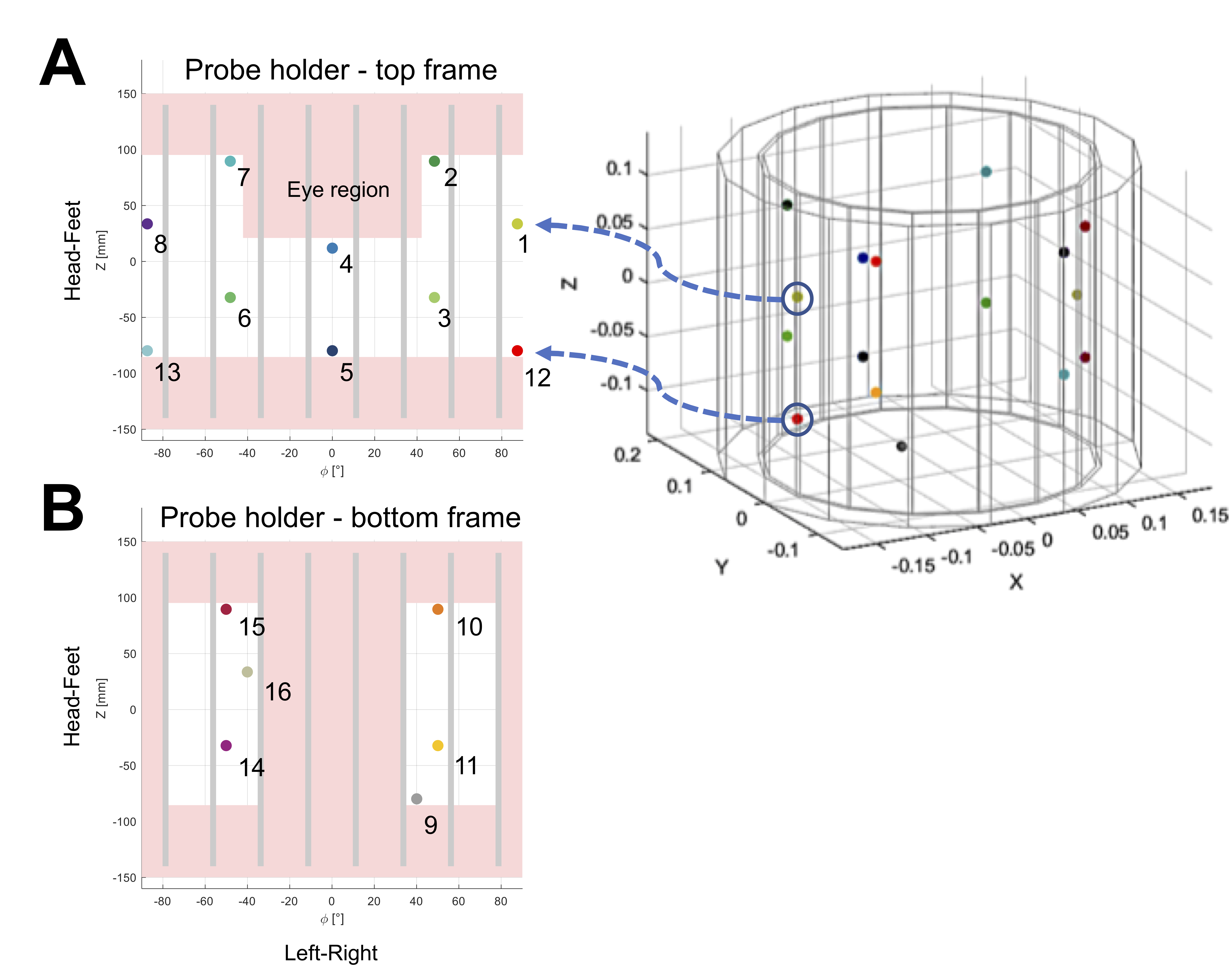
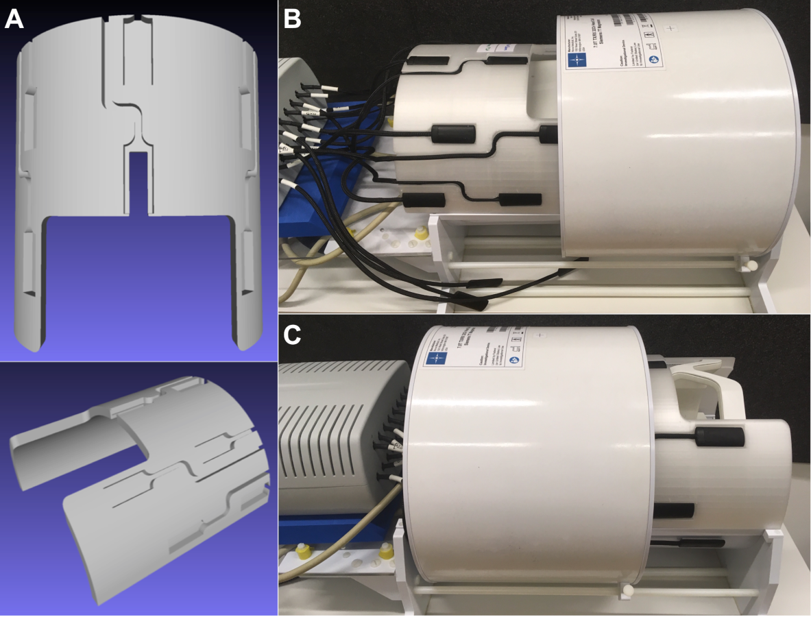
All experiments were carried out on a 7T Magnetom scanner (Siemens, Healthineers) with 16 19F field probes (Skope) and a 1Tx/32Rx head coil (Nova Medical). The geometric and empirically determined electric constraints reduce the available spots for field probe placement within a limited cylindrical space between the Tx and Rx part of the Nova coil, as depicted in Figure 1. The final probe positions on the polylactide (PLA, “MR-invisible”) frame (Figure 2) were optimized for best matching the spherical arrangement of the dynamic field camera (7). The spatial distribution of the field probe array permits expansion of the integral of the magnetic field magnitude at the probe position in terms of suitable spatial basis functions $$$f_l(\boldsymbol{r})$$$. Following the notation of (8), positioning of the probes defines the conditioning of the linear system that needs to be solved to determine $$$\boldsymbol{k}(t)$$$ based on the measured probe phase values. The noise covariance can help to assess the quality of the positioning$$$cov{_P} = (P^T P)^{-1}$$$
where $$$\boldsymbol{P}$$$ is the probing matrix that collects the values of $$$N_L$$$ basis functions at the different positions of $$$N_P$$$ probes with an individual gyromagnetic ratio $$$\gamma_P$$$:
$$$\boldsymbol{P} = \frac{\gamma_P}{\gamma}\begin{pmatrix}f_0(\boldsymbol{r}_1) & f_1(\boldsymbol{r}_1) & \ldots & f_{N_L-1}(\boldsymbol{r}_1)\\\vdots & \vdots & & \vdots\\f_{0}(\boldsymbol{r}_{N_P}) & f_1(\boldsymbol{r}_{N_P}) & \ldots & f_{N_L-1}(\boldsymbol{r}_{N_P})\end{pmatrix}$$$
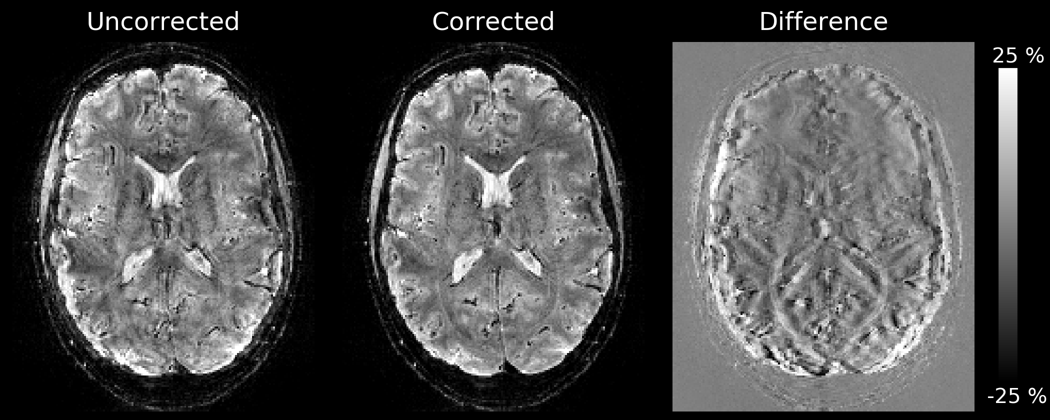
A high-resolution PD-weighted 3D-EPI (9) whole-brain measurement (1mm isotropic, R=3x1, FOV=(196x196x160)mm3, TE/TRshot =18 ms/31.3 ms, TRvol =25 s, 1.11 ms echo spacing, FA=6°, 5-fold segmented along first PE direction) was carried out using the proposed field probe holder. A 3 ms gradient-free snapshot window (2) was included before each EPI readout to first assess, and then correct for 0th and 1st order field fluctuations per shot (10). The subject was instructed to breathe heavily.
Results
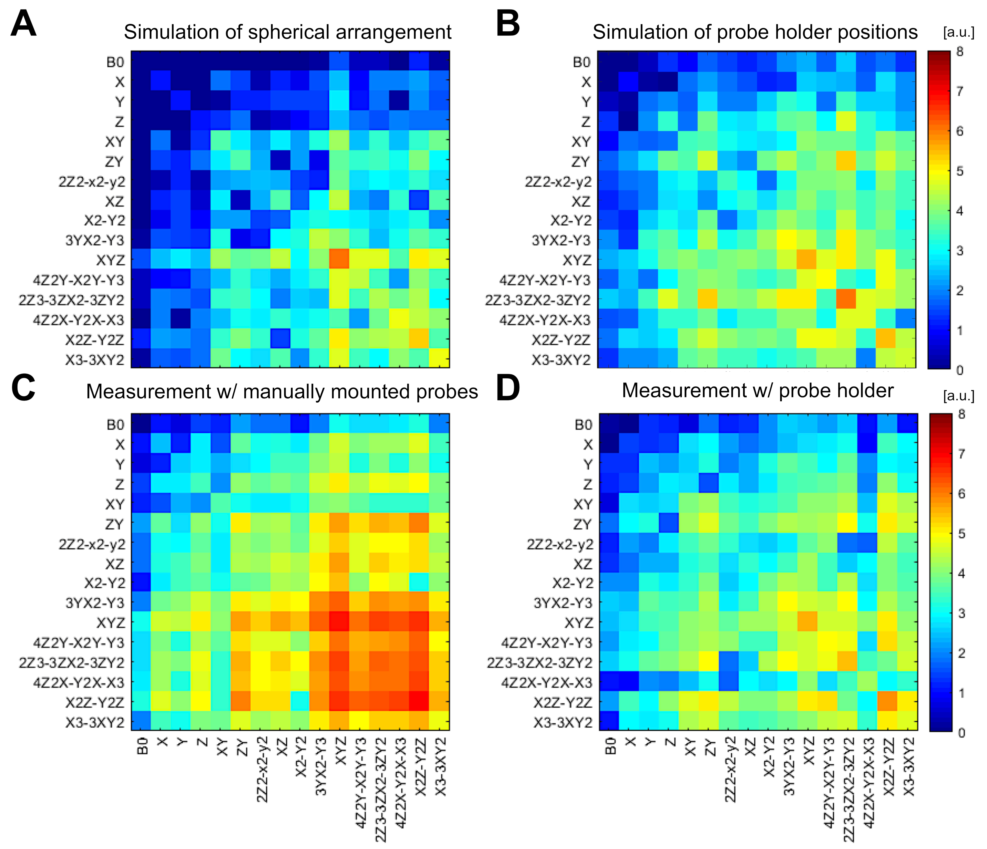
Based on the simulations, a configuration was found that gives a level of conditioning close to that of a spherical arrangement with slightly higher noise amplification levels, especially for the 2nd and 3rd order terms (Figure 3A/B). The directly measured noise covariance matrix for the probe holder (Figure 3D) shows a very good qualitative agreement with the corresponding simulation (Figure 3B) and provides a much lower noise amplification level in comparison to manual probe placement. The use of field probes mounted on the PLA frame provided a reproducible setup for 3D-EPI respiration artifact correction (Figure 4).Discussion & Conclusion
This work presents a prototype holder for the integration of a commercially available field probe system into a commercial available head coil at 7T. The setup enables robust and repeatable field probe measurements. The probe holder can be mounted or unmounted in very short time of a few minutes. The approach may serve as a blueprint for other sites that intend to use the field probe system regularly. While RF coils with integrated field probes may be a desirable future goal, the presented combination of the Skope field camera, the Nova 1Tx/32 RX head coil, and our custom field probe holder, provides a robust interim solution based on well-known and high-performing individual components.Acknowledgements
The authors thank Simon Gross (Institute for Biomedical Engineering, ETH and University of Zurich, Switzerland) for his valuable input on the probe conditioning.References
(1) De Zanche N, Barmet C, Nordmeyer-Massner JA, Pruessmann KP. NMR probes for measuring magnetic fields and field dynamics in MR systems. Magnetic Resonance in Medicine 2008;60:176–186.
(2) Vannesjo SJ, Wilm BJ, Duerst Y, Gross S, Brunner DO, Dietrich BE, Schmid T, Barmet C, Pruessmann KP. Retrospective correction of physiological field fluctuations in high-field brain MRI using concurrent field monitoring. Magnetic Resonance in Medicine 2015;73:1833–1843.
(3) Engel M, Kasper L, Barmet C, Schmid T, Vionnet L, Wilm B, Pruessmann KP. Single-shot spiral imaging at 7 T. Magnetic Resonance in Medicine 2018;80:1836–1846.
(4) Kasper L, Engel M, Barmet C, et al. Rapid anatomical brain imaging using spiral acquisition and an expanded signal model. NeuroImage 2018;168:88–100.
(5) Barmet C, Wilm B, Pavan M, Katsikatsos G, Keupp J, Mens G, Pruessmann K. Concurrent higher-order field monitoring for routine head MRI: An integrated heteronuclear setup. In: Proceedings of the 18th annual meeting of ISMRM 2010. p. 216.
(6) Schwarz JM, Pracht ED, Brenner D, Reuter M, Stöcker T. Grappa reconstructed wave-caipi MP-RAGE at 7 Tesla. Magnetic Resonance in Medicine 2018;80:2427–2438.
(7) Dietrich BE, Brunner DO, Wilm BJ, Barmet C, Gross S, Kasper L, Haeberlin M, Schmid T, Vannesjo SJ, Pruessmann KP. A field camera for MR sequence monitoring and system analysis. Magnetic Resonance in Medicine 2016;75:1831–1840.
(8) Barmet C, Zanche ND, Pruessmann KP. Spatiotemporal magnetic field monitoring for MR. Magnetic Resonance in Medicine 2008;60:187–197.
(9) Stirnberg R, Huijbers W, Brenner D, Poser BA, Breteler M, Stöcker T. Rapid whole-brain resting-state fMRI at 3 T: Efficiency-optimized three-dimensional EPI versus repetition time-matched simultaneous-multi-slice EPI. Neuroimage 2017;163:81–92.
(10) Schwarz JM, Stirnberg R, Ehses P, Stöcker T. Correction of physiological field fluctuations in high- and low-resolution 3D-EPI acquisitions at 7 Tesla. In: Proceedings of the 27th annual meeting of ISMRM 2019. p. 446.
Figures