3086
Optimization of glucose infusion protocol for glucoCEST imaging1Department of Medical Radiation Physics, Lund University, Lund, Sweden, 2Centre for Medical Imaging and Physiology, Skåne University Hospital, Lund and Malmö, Sweden, 3Russell H. Morgan Department of Radiology and Radiological Science, Johns Hopkins University School of Medicine, Baltimore, MD, United States, 4F.M. Kirby Research Center for Functional Brain Imaging, Kennedy Krieger Institute, Baltimore, MD, United States, 5College of Biomedical Engineering and Instrument Science, Zhejiang University, Hangzhou, China, 6Siemens Healthcare AB, Malmö, Sweden, 7Department of Diagnostic Radiology, Lund University, Lund, Sweden, 8Lund University Bioimaging Center, Lund University, Lund, Sweden
Synopsis
The intravenous glucose injection used in dynamic glucose-enhanced (DGE) imaging is related to transient sensations which can be unpleasant for the subject and may cause movements. We have investigated the effect of different infusion durations in terms of sensational side effects and with respect to the relation between arterial DGE signal and venous blood glucose levels. Our findings indicate that the DGE image quality does not benefit from a fast glucose injection and we conclude that a slower infusion should be used to increase patient comfort and reduce the risk for patient motion related to the glucose injection.
Introduction
In glucoCEST 1,2 (chemical exchange saturation transfer) MRI, glucose is administered intravenously, followed by registration of the change in signal over time, an approach referred to as dynamic glucose-enhanced (DGE) MRI 3-6. Glucose is a promising biodegradable alternative to gadolinium, but an intravenous glucose injection does not come entirely without side effects, such as sensational effects (e.g. pulsating sensations or warm/cold feeling in head, groin, and at injection site) and physiological responses (e.g. volumetric changes of the ventricles 7). The former can pose unpleasantness for the subject and can indirectly generate movements, while the latter can produce a DGE signal change that is not related to the CEST effect. In this study, we evaluated whether a 4-minute infusion duration could reduce unwanted effects without deteriorating the DGE image quality, as a step towards an optimized glucoCEST protocol.Methods
Written informed consent was obtained from all healthy volunteers. GlucoCEST imaging was performed with a 3T MAGNETOM Prisma scanner (Siemens Healthcare, Erlangen, Germany), using a prototype TSE sequence with saturation at a single offset of 2 ppm from the water frequency using B1 = 1.6 T for 1 second. Five subjects were imaged using a single-slice approach with a spatial resolution of 1.7x1.7x5.0 mm3, temporal resolution of 6 seconds, and TR/TE = 6000/7.1 ms. Two subjects were imaged in 3D, 8 or 10 partitions, with spatial resolution 3.3x3.3x4.0 mm3, temporal resolution 36 or 42 seconds, and TR/TE = 3000/9.0 ms. The acquisition time was approximately 15 minutes for all sequence versions. After collection of pre-infusion images, 50 ml of D-glucose (50% dextrose) was administrated intravenously in one arm via plastic tubes. The infusion duration was 1.5 minutes for four subjects (manual injection) and 4 minutes for three subjects (power injector). The glucose injection was followed by a saline flush of 30 ml, included in the infusion duration. Venous blood samples were collected in the contralateral arm before, during and after the glucoCEST data acquisition. The blood glucose level (BGL) was measured using a blood gas analyzer. The baseline BGL (average 4.7±0.9 mmol/L) was subtracted to obtain the BGL change. After the examination, the subjects were asked to orally report their experiences during the glucose injection. Image registration was performed using Elastix 8 affine transform to correct for motion. DGE maps were calculated from the signal difference between the averaged pre-infusion image and each saturated image, normalized to a non-saturated image. Arterial input functions (AIFs) were measured in 1-2 voxels in the DGE images, and the curves were temporally smoothed using a 3-point moving mean. Venous BGLs from 11 healthy subjects which underwent different glucoCEST experiments were also included in this study to improve the statistical analysis of the BGLs. Five got a short infusion (1.5 minutes), and six got a long infusion (4 minutes).Results
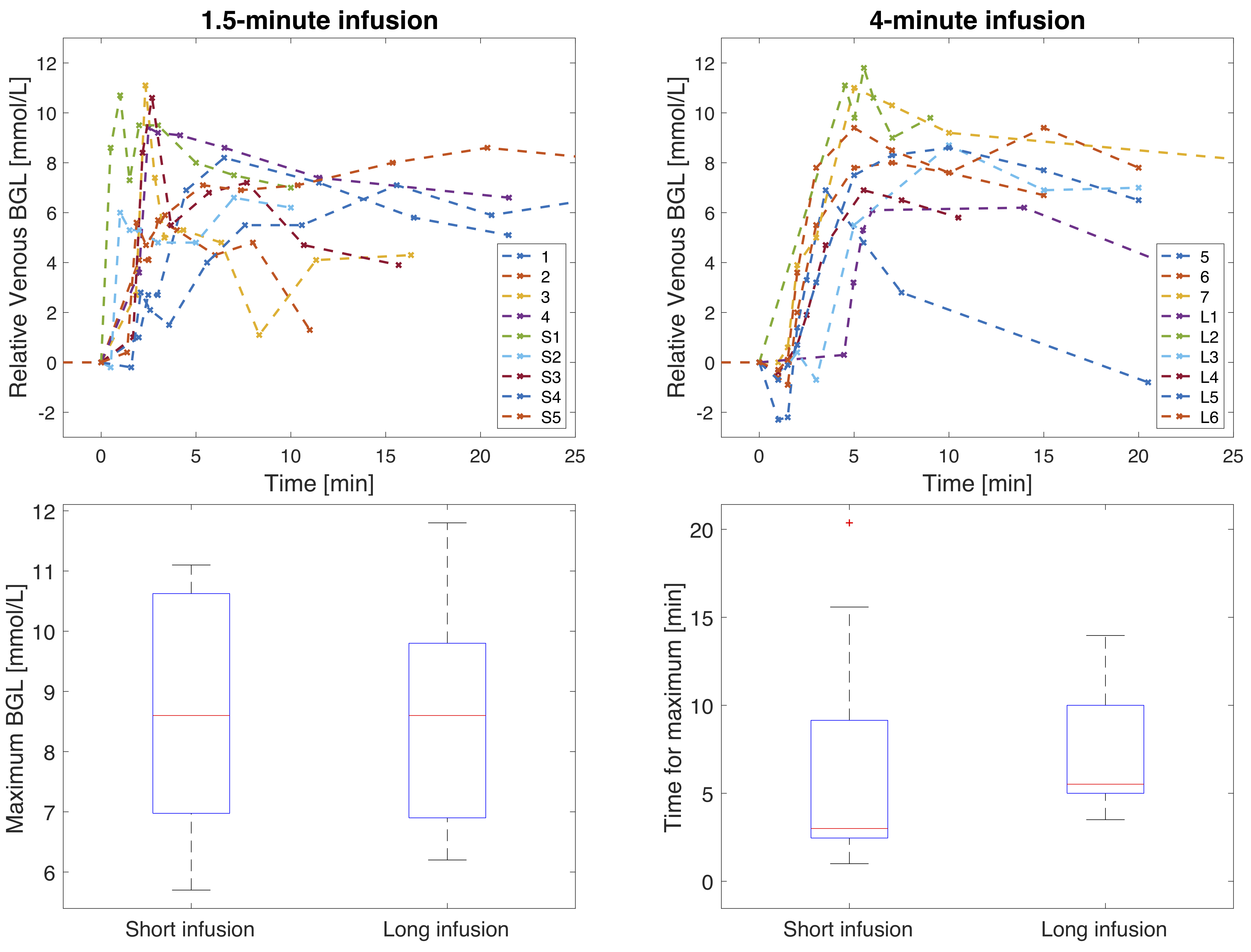
Area under the curve (AUC) DGE images for three subjects are displayed in Figure 1, all showing signal change after glucose administration. AIFs and venous BGLs for four subjects are presented in Figure 2. An increase in the arterial DGE signal can be observed after glucose injection. Figure 3 shows scatter plots of the DGE signal and the corresponding BGL. A linear regression analysis resulted in R2=0.66 for short infusion, and R2=0.82 (2D) and R2=0.72 (3D) for long infusion. BGL curves for all subjects are presented in Figure 4. The averaged maximum (±SD) BGL was 9±2 mmol/L for both the short and long infusion group. Figure 4 also includes two box plots, one showing the maximum BGL for all subjects in the two groups and one showing the corresponding time. No statistically significant difference was found in maximum BGL (p=0.9) or time to peak (p=0.8) between the two groups (two-sample t-test). A longer infusion resulted in fewer and/or weaker side effects, and some subjects did not experience any sensational side effects at all.Discussion
AIFs could be measured regardless of infusion duration. The 2D and 3D data cannot be directly compared in terms of DGE signal magnitude. One likely reason for the lower arterial DGE signal in the 3D data is the lower spatial resolution, resulting in more partial-volume effects. Motion correction is important in DGE imaging 9,10, and the difference in DGE signal magnitude can also partially be explained by the limited motion correction possible in 2D. The 3D DGE signal is actually closer to the expected effect size based on simulations 10. However, correlations between BGL and DGE signal were found in all cases. The 4-minute infusion gave a slightly later BGL peak, seen in Figure 4, and the maximum BGL was not affected, which is in accordance with earlier studies 11. A longer infusion duration has also been shown to cause less insulin response 11. The physiological responses to the glucose injection were not evaluated here, but the fact that the sensational side effects were reduced should in itself reduce the risk of subject motion during glucose infusion and can therefore improve DGE image quality.Conclusion
This study indicates that a 4-minute infusion duration resulted in fewer sensational side effects compared to a 1.5-minute infusion duration without negatively affecting the DGE image quality.Acknowledgements
No acknowledgement found.References
1. Chan KW, McMahon MT, Kato Y, et al. Natural D-glucose as a biodegradable MRI contrast agent for detecting cancer. Magn Reson Med 2012;68(6):1764–1773.
2. Walker-Samuel S, Ramasawmy R, Torrealdea F, et al. In vivo imaging of glucose uptake and metabolism in tumors. Nat Med 2013;19(8):1067-72.
3. Xu X, Yadav NN, Knutsson L, et al. Dynamic glucose enhanced (DGE) MRI: Translation to human scanning and first results in glioma patients. Tomography 2015;1(2):105-14.
4. Xu X, Chan KWY, Knutsson L, et al. Dynamic glucose enhanced (DGE) MRI for combined imaging of blood–brain barrier break down and increased blood volume in brain cancer. Magn Reson Med 2015; 74(6):1556-1563.
5. Paech D, Schuenke P, Koehler C, et al. T1ρ-weighted dynamic glucose-enhanced MR imaging in the human brain. Radiology 2017;285(3):914–922.
6. Schuenke P, Paech D, Koehler C, et al. Fast and quantitative T1ρ-weighted dynamic glucose enhanced MRI. Sci Rep 2017;7:42093
7. Puri BK, Lewis HJ, Saeed N, Davey NJ. Volumetric change of the lateral ventricles in the human brain following glucose loading. Exp Physiol 1999;84(1):223-226.
8. Klein S, et al. Elastix: a toolbox for intensity based medical image registration. IEEE Trans Med Imaging. 2010; 29(1):196–205.
9. Zaiss M, Herz K, Deshmane A, et al. Possible artifacts in dynamic CEST MRI due to motion and field alterations. J Magn Reson 2019;298:16-22.
10. Xu X, Seidemo A, Sehgal AA, Knutsson L, et al. Dynamic glucose enhanced imaging at 3T: Effects of physiological changes and motion. Proceedings of the International Society of Magnetic Resonance in Medicine, abstract number 5016, 2019.
11. Chen M, Porte D. The effect of rate and dose of glucose infusion on the acute insulin response in man. JCEM 1976;42(6):1168–1175.
12. Seidemo A, Rydhög A, Wirestam R, et al. Comparison between glucoCEST at 3T and blood glucose sampling in humans. Proceedings of the International Society of Magnetic Resonance in Medicine, abstract number 4999, 2019.
Figures