2976
Comparison Between Single Channel Dual Loop 23Na Coil and 6-Channel Flexible Wraparound 23Na Coil for Renal Sodium Imaging1University of Nottingham, Nottingham, United Kingdom, 2Philips Healthcare, Guildford, United Kingdom
Synopsis
Sodium (23Na) MRI has the potential to provide insight to many diseases however 23Na MRI requires nonstandard hardware. This work compares two different designs of RF coil; a single channel pair of transmit-receive (Tx/Rx) loops and a 1Tx-6Rx flexible wraparound coil. Firstly, a 3D gradient-recalled-echo (GRE) sequence was optimised for each coil, then the signal-to-noise ratio (SNR) and field of view (FOV) was compared in both a phantom and in-vivo in a healthy control. SNR was 7±3 and 12±4 for the loops coil and the 6-channel coil respectively.
Introduction
Sodium is the second most abundant NMR sensitive nucleus in the body. 23Na MRI of the kidney has been shown to provide the sensitivity to measure the corticomedullary sodium gradient (CMSG), which serves to regulate homeostasis, and has been demonstrated to be reduced in kidney disease and transplanted kidneys1,2. However, the low sensitivity of 23Na MRI in the body and the need for additional hardware and specialised RF coils has limited its use. Further benefit of 23Na MRI comes with the fusion of 23Na images with 1H morphological and functional images to produce co-located complementary information, for this the collection of 23Na and 1H images within a single scan session without moving the subject is required. Here we compare linear and quadrature 23Na transmit coils and the use of multi-receive elements for 23Na of the abdomen using an optimised 3D GRE imaging sequence.Methods
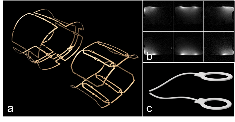
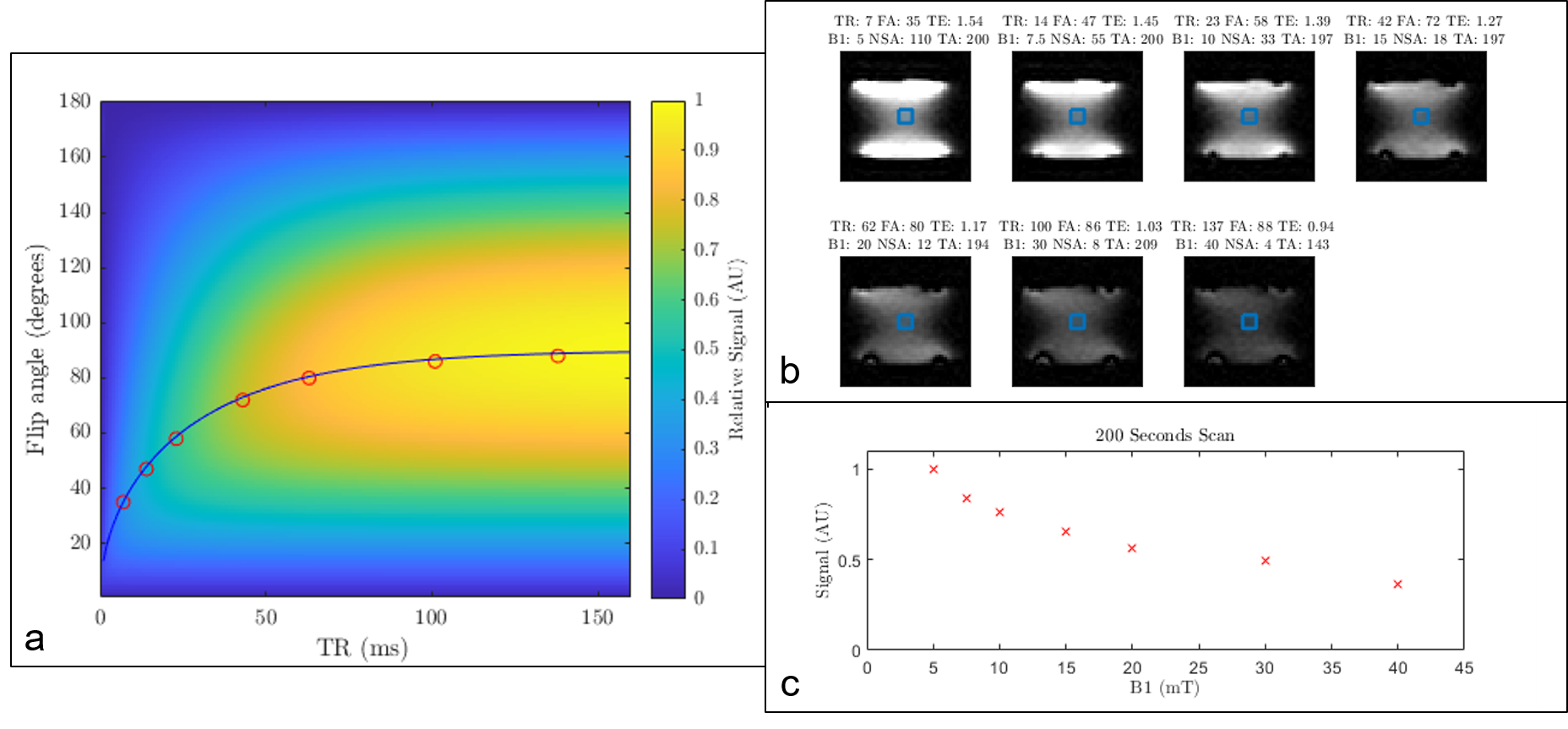
RF coil design: We collected 23Na imaging data on a Philips 3T DDAS-MN Ingenia system using two different RF coil designs (Figure 1): 1) a single channel dual loop transmit-receive (Tx/Rx) coil (PulseTeq Ltd., Surrey, UK). The loops are flexible and padded allowing for versatile positioning on a subject. Each loop is placed either side of the imaging region and they act as a Helmholtz pair; 2) a quadrature transmit and 6-channel receive wraparound 23NA coil (Clinical MR solutions, Brookfield, Wi). The coil comprises of an outside layer containing transmit loops arranged and driven in quadrature, and an inner layer containing two sets of three receive loops. SAR modelling of the coil was performed in REMCOM XFdtd software and RF-induced heating evaluated using a fibre optic thermometer prior to use in-vivo. 1H images were acquired without moving the subject, using the in-built Q-body coil.Sequence optimisation: All data acquisition was performed using a 3D GRE sequence, as simulated in Figure 2a. In order to ascertain the optimal combination of parameters a series of 10 x 10 x 30 mm3 scans on phantoms were carried out using pulses with B1 = (5,7.5,10,15,20,30,40)mT at the maximum Ernst angle the average RF power limit would allow. Each scan was carried out twice, one with a single average and the other with a number of averages such that the total acquisition approximately 200 seconds long. The same scans were then carried out in-vivo in a healthy control to validate optimisation.
Data Acquisition: To compare the coils performance a 20-minute 23Na 3D GRE acquisition was carried out on a 100 mmol/L 23Na 20L phantom using the following optimum parameters:
Loops: TR: 8ms, TE: 1.75ms, FA: 35, resolution 5x5x20mm3, TA: 20mins, NSA: 406
6-channel: TR: 25ms, TE: 1.97ms, FA: 44, resolution 5x5x20mm3, TA 20mins, NSA: 130
Identical scans were carried out in-vivo to allow direct comparison. In addition, in-vivo a 1H T1W B-TFE 1.8x1.8x15mm3 scan was acquired for high-resolution segmentation of the kidney to be applied to the 23Na images, as well as a 12 echo mFFE for renal BOLD.
Data Processing: The six receive channels signals were combined using a sum-of-squares combination3. SNR in the 23Na image was computed by defining regions of interest (ROI) of similar size and location as the kidneys in the body in the phantom images and comparing it to the signal inside an ROI of background noise.
Results
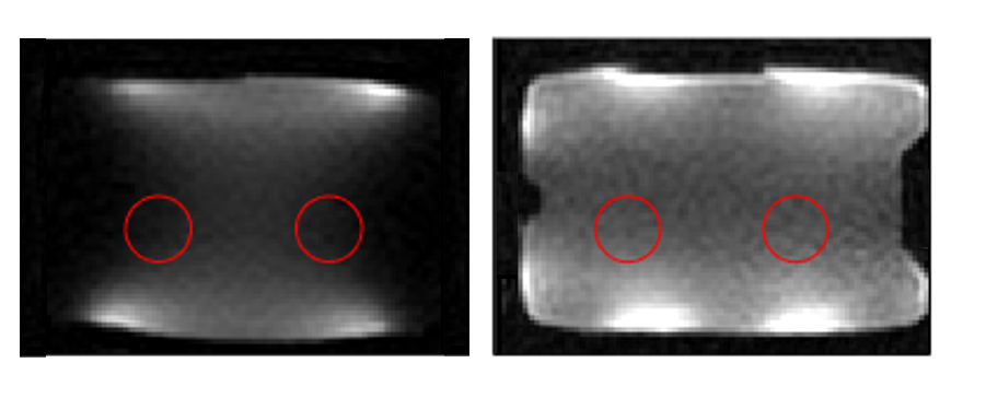
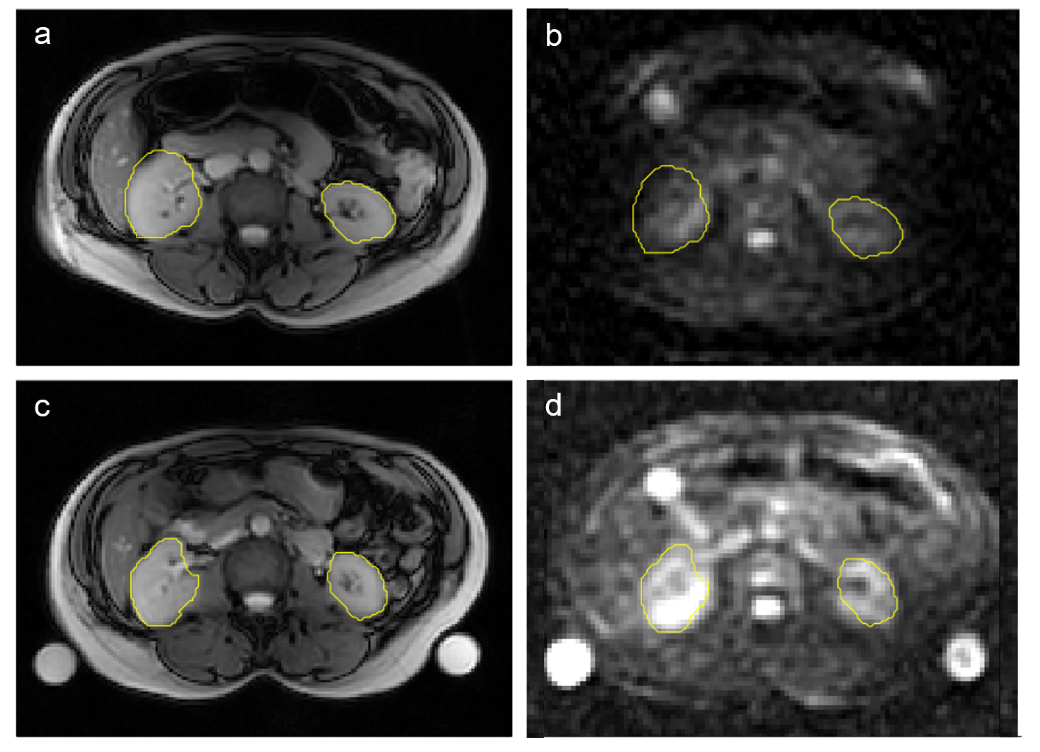
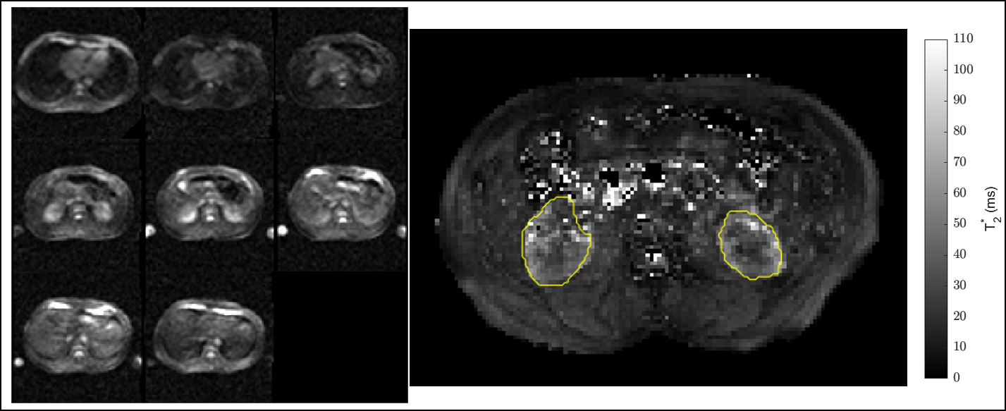
Results from the parameter optimisation can be seen in Figure 2, it can be see that use of a small TR provides the greatest SNR per unit time for both the loops coil and the 6-channel coil. The loops coil has a higher transmit efficiently meaning the required B1 could be reached with less RF power, allowing use of a shorter TR and higher NSA, while keeping within the average power limit. Figure 3 shows the 23Na image of the phantom acquired using each coil. The SNR in the ROIs are 6±2 and 19±3 for the loop and 6-channel coil respectively. Figure 4 shows the same acquisition carried out in-vivo using each coil and the associated 1H image was used to segment the kidneys, the SNR inside the kidneys was 7±3 and 12±4 for the loop and 6-channel coil respectively. Figure 5 demonstrates the FOV of the 6-channel coil and the ability to carry out a T2* scanning in the same session.Discussion
The optimum parameters were found for a GRE sequence for 23Na abdominal imaging. The 6-channel coil provided a higher SNR than the loops coil in both phantom and in-vivo due to the combination of the signal from the individual six receive channels, despite the greater transmit efficiency of the loops coil. Further, the six channels provided a greater FOV and with larger subjects the kidneys would not be within the optimum sensitivity region of the loops coils. The sum-of-square method increases the noise when the channels combined, other methods of channel combination can be used to reduce this effect4 which will provide a further increase of SNR. Further investigations into the B1 homogeneity of the two coils is also needed.Conclusion
Optimised 23Na imaging of the abdomen has been demonstrated. In future an ultrashort TE sequences5 will be implemented to capture the short T2 23Na decay and increase SNR.Acknowledgements
This work was supported by a Discovery Grant from the Medical Research Council: “23Na MRI: New frontiers in clinical imaging and diagnostics”References
1. Haneder, S. et al. 3T Renal 23Na-MRI: effects of desmopressin in patients with central diabetes insipidus. Magn. Reson. Mater. Physics, Biol. Med. 27, 47–52 (2014).
2. Moon, C. H. et al. Quantitative sodium MR imaging of native versus transplanted kidneys using a dual-tuned proton/sodium (1H/23Na) coil: Initial experience. Eur. Radiol. 24, 1320–1326 (2014).
3. Roemer, P. B., Edelstein, W. A., Hayes, C. E., Souza, S. P. & Mueller, O. M. The NMR phased array. Magn. Reson. Med. 16, 192–225 (1990).
4. Benkhedah, N., Hoffmann, S. H., Biller, A. & Nagel, A. M. Evaluation of adaptive combination of 30-channel head receive coil array data in 23Na MR imaging. Magn. Reson. Med. 75, 527–536 (2016).
5. Nielles-Vallespin, S. et al. 3D radial projection technique with ultrashort echo times for sodium MRI: clinical applications in human brain and skeletal muscle. Magn. Reson. Med. 57, 74–81 (2007).
Figures