2876
Large denoising effect of ultrahigh dielectric constant (uHDC) materials1Department of Neurosurgery, PennState University College of Medicine, Hershey, PA, United States, 2Department of Radiology, PennState University College of Medicine, Hershey, PA, United States, 3CMRR, Department of Radiology, University of Minnesota, Minneapolis, MN, United States, 4Department of Engineering Science and Mechanics, Pennsylvania State University, State College, PA, United States
Synopsis
We investigated the effect of ultrahigh dielectric constant (uHDC) materials on reducing the noise and enhancing B1 efficiency at 78-MHz for low-γ nuclear applications (23Na and 13C at 7T or 61-MHz for 17O at 10.5 T). By employing uHDC materials, the conservative E-field can be reduced in the sample, which makes the non-conservative field dominant and increases the transmit efficiency and receive sensitivity. We calculated the normalized noise level and extracted the B1+ efficiency map for baseline (no uHDC) and when uHDC is used, and show experimentally that noise level is reduced considerably in the presence of the UHDC material.
Introduction
It was shown previously that RF B1 field can be enhanced several folds in the sample by induced strong displacement current in high dielectric constant (uHDC) materials next to the sample 1, 2. The displacement current in uHDC materials is produced by non-conservative E field by the coil. However, the E field by the RF coils in the sample consists of both conservative and non-conservative components (Eq. 1), both of which produce losses and generate noises in a conductive sample 3.$$\overrightarrow{E}=\overrightarrow{E}_{Conservative}+\overrightarrow{E}_{Non-Conservative}=-\overrightarrow{\triangledown\phi}-j\omega\overrightarrow{A} (1)$$
where φ is the electric scalar potential, is the vector potential, and ω is the angular frequency. Since one of the properties of UHDC material is partial shielding the conservative E-field, in this investigation, we studied the effect of suppression of noise level by the uHDC materials via shielding the conservative E-field at 78 MHz (23Na and 13C at 7T or 61 MHz for 17O at 10.5T). We demonstrate that this de-noising effect of HDC material could synergistically enhance the SNR further by the induced displacement current in the material.
Methods
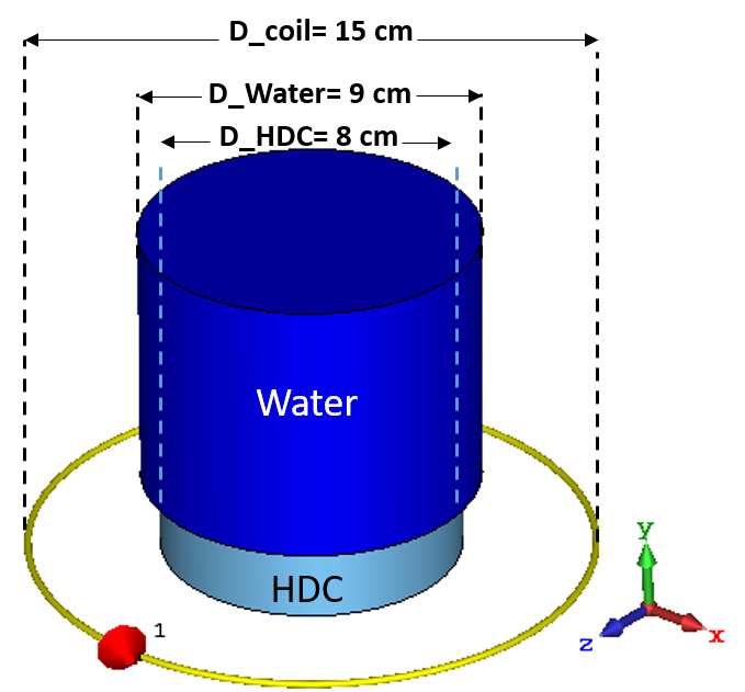
Simulation setup: We performed the simulation in CST Microwave Studio as a full-wave simulation software. The setup (Fig.1) includes a 15 cm diameter coil shaped from a copper wire, a cylindrical uHDC disk, and a cylindrical water phantom placed on top of the uHDC disk. The thickness and diameter of the uHDC disk is chosen as 2.1 cm and 8 cm, respectively. The water phantom is filled within a container with the diameter of 9 cm and height of 11 cm. The phantom has the relative permittivity εr=80 and conductivity of σ=1.5 S/m. The coil diameter is chosen 15 cm so that the tuning and matching of the coil at the desired frequency (78.6 and 61 MHz) is easier. To perform our investigation, we studied the field at employing high relative permittivity values of the HDC material at εr = 6000, and compared the noise level and the B1+ efficiency.Electric field map: has been extracted and compared for the 1) coil only (without uHDC disk and phantom), 2) coil and phantom in the coil center (baseline), and 3) the coil with phantom in the center on top of the HDC disk.
SNR gain and Noise Level (NL): The SNR is calculated from the signal produced by the coil over the noise level calculated from Roemer et al. 3, which can also be presented as the dissipated power within the phantom. In this work we calculated the normalized noise level (NNL) over the average value of the B1 field within the phantom (Eq. 2).
$$ NNL=\sqrt{\frac{\int_{}^{}\sigma|E|^{2}dv }{avg(|B_{1}^+|^{2})}} (2)$$
where σ is the conductivity of the phantom, and E is the electric field. The integration is performed in the whole volume of the phantom.
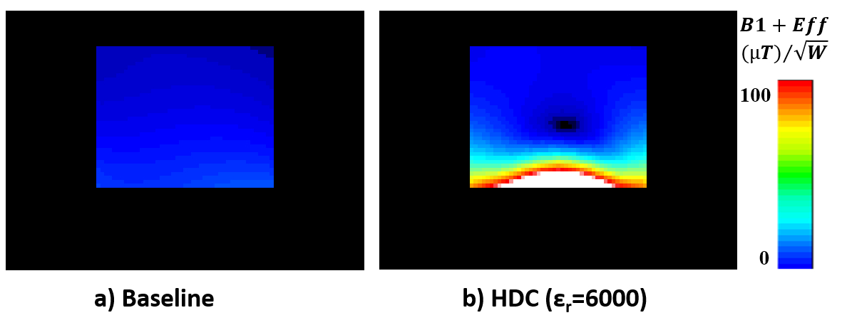
B1+ Efficiency: The B1 field is decomposed into two counter rotating fields in the transvers plane, B1+ and B1-. Then the efficiency is calculated by dividing the B1+ over the square root of the dissipated power within the phantom.
Results and Discussion
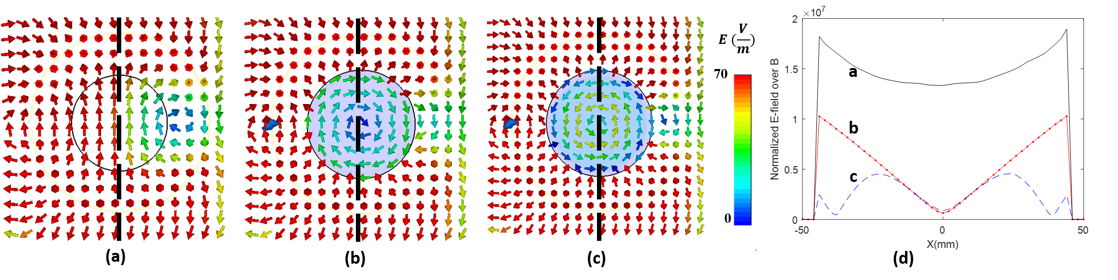
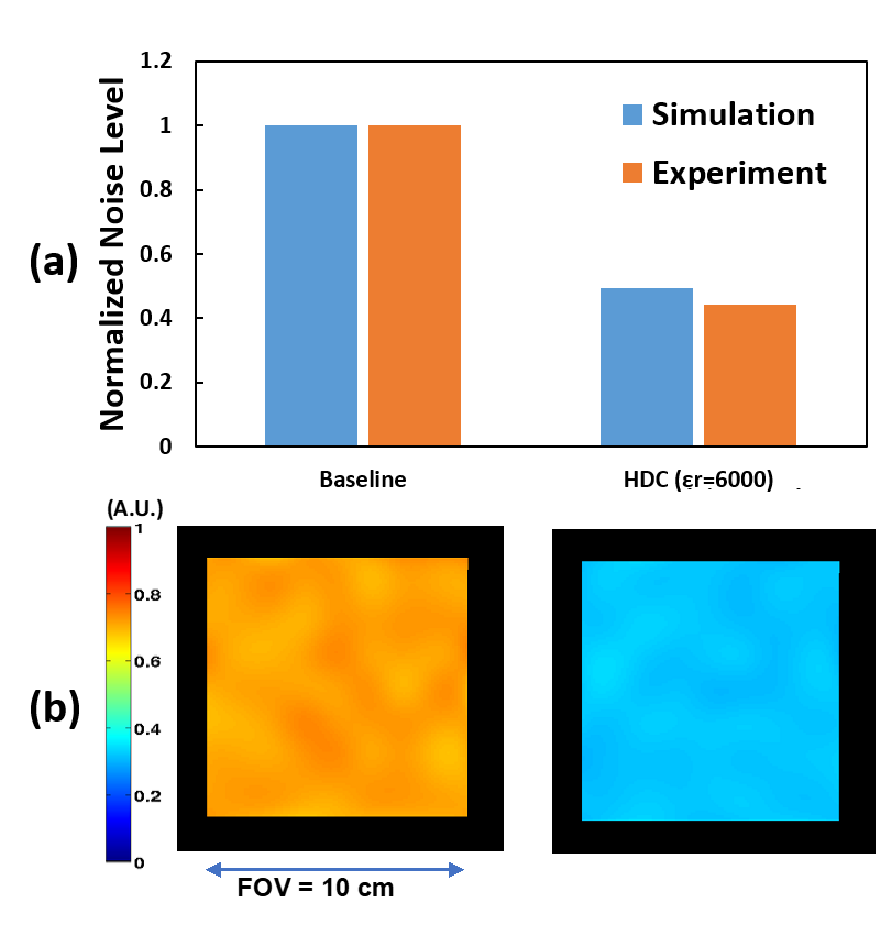
The vector plots in Fig.2a shows that the E-field in the sample region for coil-only case consists of a set of parallel lines indicating a conservative field. In the presence of the phantom (Fig. 2b) the E-field vectors in the phantom follow circular lines, indicating the field is dominantly non-conservative, while outside the sample E-field is dominantly conservative. The conservative E-field is produced by the surface charges of the coil and phantom. The E-field intensity is also decreased within the phantom. However, in the presence of the uHDC disk we see the non-conservative E-field is enhanced, which in turn, creates displacement current and induces a much stronger B1 field in the sample. The line plot in Fig.2d shows the conservative field is reduced by the uHDC disk, which leads to a significant reduction of the noise level. Figure 3a shows the calculated and experimental normalized noise level, the noise level is reduced by approximately 50% with the uHDC disk of that of baseline. Figure 3b shows the experimental results of 17O MRSI noise levels between baseline and in the presence of the uHDC disk. This denoising effect which were achieved through a reduction of the conservative E-field contribution by the uHDC disk. Figure 4 also shows the B1+ efficiency maps without and with uHDC disk. As we see, the B1 efficiency is enhanced substantially by using the uHDC disk.Conclusion
With computer modeling and experimental measurements under an identical setup, we demonstrated that, in addition to B1 field enhancement by the induced displacement current, the uHDC material can also shield the conservative E-field in the sample. This property leads to a prominent denoising effect. This effect can immediately benefit imaging of 23Na and 13C at 7T and 17O at 10.5T.Acknowledgements
This work was supported in part by NIH grants of U01 EB026978, R24 MH106049, R01 CA240953, S10 RR026783 and P41 EB027061.References
[1] Yang, Q.X. et al., JMRI, 2013. 38(2).
[2] Rupprecht, S., et al., Magnetic Resonance in Medicine, 2017. 79(5).
[3] Roemer, P. B., et al., Magnetic Resonance in Medicine, 1990, 16(2)
Figures