1276
Low-profile AC/DC coils without RF Chokes1Department of Biomedical Engineering, Vanderbilt University, Nashville, TN, United States, 2Department of Electrical Engineering, Vanderbilt University, Nashville, TN, United States, 3Vanderbilt University Institute of Imaging Science, Nashville, TN, United States, 4Department of Radiology, Vanderbilt University Medical Center, Nashville, TN, United States
Synopsis
Large RF chokes increase the inductance/resistance of the DC loop and thus lead to unwanted power dissipation and bulk. We theoretically analyzed the added coil loss induced by bridge inductors in AC/DC coils and found that large bridge chokes can be replaced by low-profile inductors with much smaller values, if the capacitance is adjusted to compensate the resonance frequency shift. This will reduce the footprint of AC/DC coils as well as the inductance/resistance and thus power dissipation, with a cost of slightly higher coil loss.
Purpose
A typical RF choke is a large inductor (typically several uH to ~tens of uH) whose self-resonance frequency is close to a desired frequency. For AC/DC coils that can simultaneously receive signal and perform B0 shimming [1-4], the number of required chokes increases as the coil size and static magnetic field increase. Large chokes increase the inductance/resistance of the DC loop and thus lead to unwanted power dissipation and bulk when space is limited, such as in a multi-channel receive/shim array or in the presence of a focused ultrasound system. Although mono transmission line resonators can obviate the use of large chokes in AC/DC coils, they require special manufacturing and are not readily feasible for use as an imaging coil in terms of size, geometry, or shape [5]. In this work, we analyze the added coil loss from a bridge inductor, and then build AC/DC coils with low-profile small inductors. Bench test and MR experimental results show that the coil losses induced by the large bridge chokes can be avoided by using much smaller inductors, with an acceptable B1 efficiency tradeoff.Methods
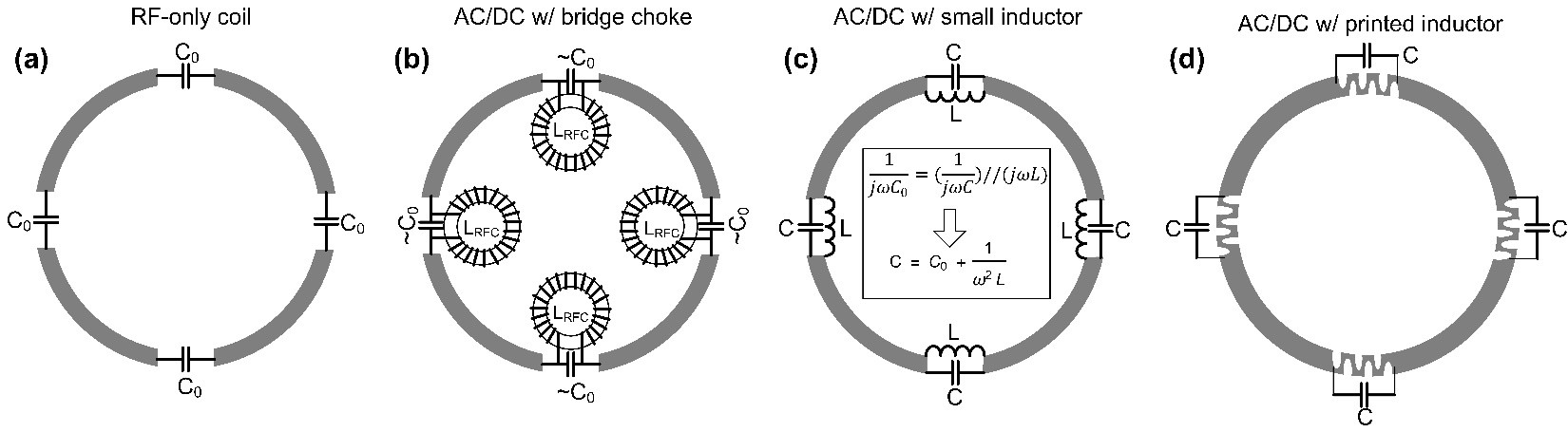
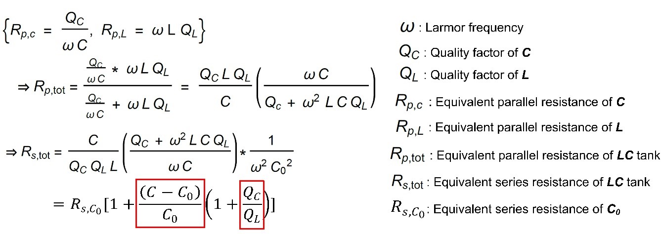
RF circuit analysisFigures 1 illustrate circuits of an RF-only coil (a), an AC/DC coil with bridge chokes (b), an AC/DC coil with small lumped-element inductors (c) and an AC/DC coil with small printed inductors (d).This LC tank circuit has the equivalent impedance of a single capacitance. Figure 2 derives the equivalent series resistance of an LC circuit, where is the equivalent series resistance of (C0), and Qc and QL are the quality factors of C and L. Based on the equation, for a given RF-only coil, the additional resistance from parallel inductors depends on two factors: 1. the inductance of the bridge inductor or the increased capacitance (C−C0)/C0 that compensates bridge inductance; 2. the Q-factor ratio of the bridge inductor versus the capacitor. Although small inductors shift the resonance frequency more and C deviates more from C0, they have relatively higher Q.
Coil fabrication, bench tests and MR experiment
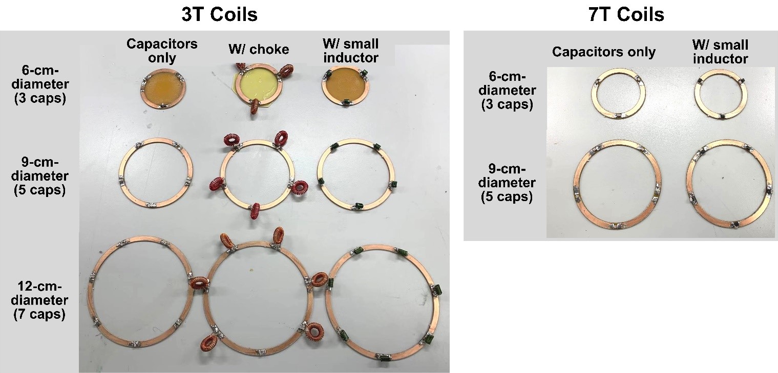
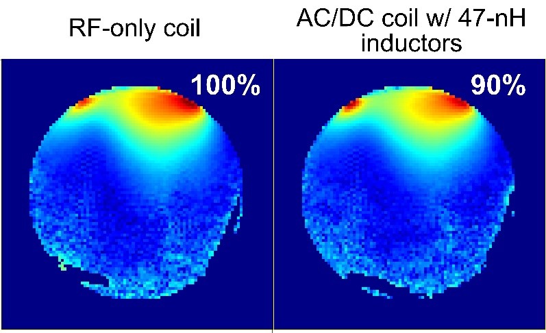
We built three AC/DC coils for 3T with different sizes, as shown in Figure 3, left. The inductance used to bridge the capacitors was ~130 nH (Coil Craft, 2222SQ-131), which is much smaller than a bridge choke of several uH. To compensate for the frequency shift of the bridge inductor, the distribution capacitance increased ~30%. The typical Q-factors of a 20-pF capacitor and 130-nH inductor are 1000 and 200 at 128 MHz, respectively. Therefore, the series resistance of the capacitor is amplified by 2x based on the equations in Figure 2. For comparison, we built RF-only coils and AC/DC coils with large bridge chokes. The Q-factor of capacitors decreases as the frequency increases, while the Q-factor of inductors increases as the frequency increases. Typical Q-factor of a 10-pF capacitor and a 47-nH inductor (Coil Craft, 1515SQ-47N) are around 500 and 300, respectively. At 7T, the inductance can be further reduced without amplifying the bridge circuit's series resistance much. Herein we built 6-cm-diameter and 9-cm-diameter AC/DC coils with bridge inductors of only 47nH for 7T (Figure 3, right). We measured all coils' unloaded Q-factors in free space and loaded Q-factors on a 15-cm-diameter ball phantom (1% agar, 0.1% Gd, 1% salt, and 0.05% sodium azide) with a highly decoupled double probe. We also acquired B1+ maps on a ball phantom with the 7T 9-cm-diameter AC/DC coil (with 47-nH inductor) and the 7T 9-cm-diameter RF-only coil. The B1+ maps were measured with the DREAM method on a 7T whole-body scanner (Philips Healthcare, Best, Netherlands).
Results
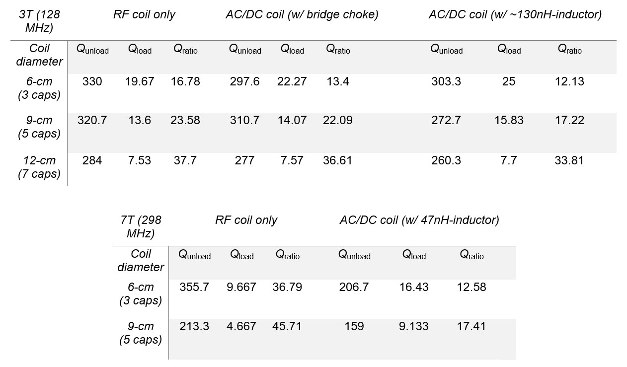
Figure 4 shows the Q-factor comparisons at 3T and 7T. As expected, the RF-only coil has the highest unloaded-to-loaded Q-factor ratio and the lowest coil noise. The Q-factor ratios of the small-inductor low-profile AC/DC coils are similar to those of the choke-bridged AC/DC coils. Figure 5 shows transmit efficiency (B1+) maps of an RF-only coil and a 47-nH-inductor-bridged AC/DC coil. The small-inductor AC/DC coil only has slightly lower efficiency compared to the RF-only coil, which is consistent with the bench test results in Figure 4. Based on the theoretical analysis and bench test, we found that the inductance of the added inductor could be made much smaller at higher fields without increasing coil loss. Therefore, the small-inductor AC/DC coil becomes more advantageous at ultrahigh fields, especially considering that more bridge inductors are needed. Although the small inductor is not self-shielded, we believe it will not affect the local B0 field since it has a much lower profile and many fewer turns compared to an RF chokes. Further studies will investigate whether the small lumped inductors can be replaced with printed copper traces that take minimum space, as shown in Figure 1d.Discussion and Conclusion
We theoretically analyzed the added coil loss induced by bridge inductors in AC/DC coils and found that large bridge chokes can be replaced by low-profile inductors with much smaller values, if the capacitance is adjusted to compensate the resonance frequency shift. This will reduce the footprint of AC/DC coils as well as the inductance/resistance and thus power dissipation, with a cost of slightly higher coil loss. The coils may also enable faster B0 shim switching.Acknowledgements
This work was supported by NIH Grants U18 EB 029351, R01 EB 016695, and U01 EB 025162 .References
1. Han H, Song AW, Truong TK. Integrated parallel reception, excitation, and shimming (iPRES). Magn Reson Med. 2013; 70: 241– 247.
2. Stockmann J, Blau JN, Zhao W, Polimeni JR, Wald LL. Combined shim‐RF array for highly efficient shimming of the brain at 7 Tesla. In Proceedings of the 21st Annual Meeting of ISMRM, Salt Lake City, UT, 2013. p. 665.
3. Stockmann JP, Witzel T, Keil B, et al. A 32‐channel combined RF and B0 shim array for 3T brain imaging. Magn Reson Med. 2016; 75: 441– 451.
4. Truong TK, Darnell D, Song AW. Integrated RF/shim coil array for parallel reception and localized B0 shimming in the human brain. NeuroImage. 2014; 103: 235– 240.
5. Stara R, Pendse M, Stockmann JP, Rutt BK. Monolithic transmitline resonator as a combined B1/B0-shim coil element.Proc IntSoc Magn Res. 2017;25:0968.
Figures