1275
Imaging artefacts during simultaneous in-beam MR imaging and proton pencil beam irradiation1Institute of Radiooncology-OncoRay, Helmholtz-Zentrum Dresden - Rossendorf, Dresden, Germany, 2OncoRay – National Center for Radiation Research in Oncology, Faculty of Medicine and University Hospital Carl Gustav Carus, Technische Universität Dresden, Helmholtz-Zentrum Dresden-Rossendorf, Dresden, Germany, 3Department of Radiology, Faculty of Medicine and University Hospital Carl Gustav Carus, Technische Universität Dresden, Dresden, Germany, 4Technische Universität Dresden, Carl Gustav Carus Faculty of Medicine, Dresden, Germany, 5Department of Radiotherapy and Radiation Oncology, Faculty of Medicine and University Hospital Carl Gustav Carus, Technische Universität Dresden, Dresden, Germany
Synopsis
The targeting precision of proton therapy is expected to benefit from real-time MRI guidance. We developed a setup of a first prototype in-beam MRI scanner with a proton pencil beam scanning nozzle. Dipole magnets in the nozzle used for beam steering produce time-dependent magnetic fringe fields that may interfere with the MR image acquisition. In this study, we show that vertical beam steering shows no degradation of the MR image quality, whereas horizontal beam steering introduces severe ghosting artefacts in phase encoding direction. The origin of these artefacts is unraveled and strategies to eliminate or correct these artefacts are proposed.
Introduction
Real-time MRI guidance is expected to significantly improve the targeting precision of proton therapy (PT) 1. Hybrid systems integrating MRI and PT do not exist due to a number of hitherto open technological questions. To assess the mutual magnetic interactions between these systems, we recently realized a setup of a first prototype in-beam MRI scanner at a horizontal proton pencil beam scanning (PBS) research beamline. The static and dynamic magnetic fringe fields produced by the PBS beamline may interfere with the imaging fields of the MRI scanner. The aim of this study was to investigate the effects of the dynamic fringe fields of the PBS beamline on the MR image quality during simultaneous proton beam irradiation and MR image acquisition.Methods
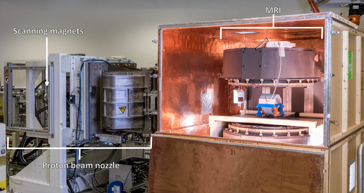
A 0.22 T C-shaped open MR scanner (MrJ2200, ASG Superconductors S.p.A., Genua, Italy) was combined with a horizontal PBS research beamline connected to an isochronous cyclotron (C230, Ion Beam Applications SA, Louvain-la-Neuve, Belgium). The scanner was mounted on a mobile transport platform and enclosed by a Faraday cage made of plywood panels and a 120 µm copper foil (Fig. 1) 2. Volumetric irradiation is achieved by magnetic beam steering in horizontal and vertical direction by a pair of dipole magnets (scanning magnets), whereas the depth variation is determined by the initial energy of the proton beam.To investigate the time-dependent beam steering effects on the MR image quality a proton beam of 220 MeV was subsequently scanned along either a horizontal or vertical line of 40 cm and 20 cm length, respectively, using 9, 17, 33 and 81 equidistant dose spots. The total irradiation time of 20 s was matched to the acquisition time of a single-slice gradient echo (GRE) sequence (TE=20 ms, TR=80 ms, FA=60°, FOV=20×20 cm2, acquisition matrix=256×256, bandwidth=42 Hz/px, Cartesian sampling) that was used to image a homogeneous transversal slice of the ACR Small Phantom 3, being positioned inside a knee receiver coil in the center of the field-of-view of the MR scanner.
Imaging and irradiation was manually synchronized such that image acquisition started ~1 s before beam scanning, to assure that the pre-image frequency calibration was unaffected by magnetic field changes due to the scanning of the proton beam. The MR image quality was qualitatively evaluated and compared to reference images acquired without beam scanning but with the beamline energized.
Results
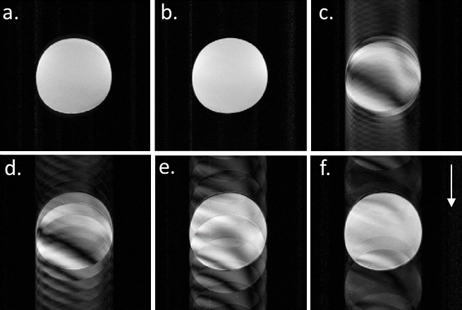
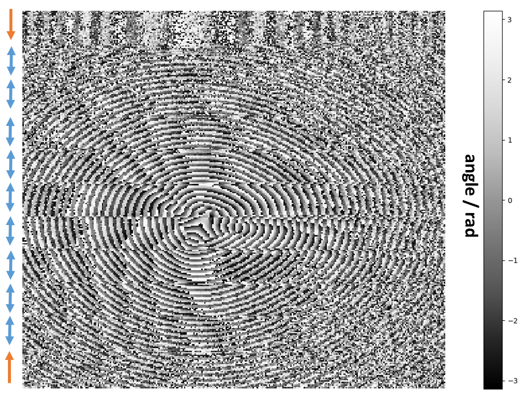
MR images acquired during vertical beam scanning showed no visual differences to reference images (Fig. 2a-b). This indicates that vertical beam scanning does not deteriorate the MR image quality. The MR images acquired during horizontal beam scanning, however, are blurred and show coherent ghosting artefacts in the phase encoding (PE) direction (Fig. 2c-f). The number of ghosts in the images is inversely proportional to the number of dose spots scanned. This indicates a phase mismatch between adjacent lines in k-space, caused by a change of the central resonance frequency due to the fringe field of the beam scanning magnets. This phase shift is recognized in the phase map of the k-space data (Fig. 3) and coincides with the position change between dose spots.Discussion
For the first time, the effects of the dynamic fringe fields of a proton PBS beamline on the MR image quality have been assessed during simultaneous proton beam irradiation and MR image acquisition. Severe ghosting artefacts were observed in a GRE image acquired during proton beam scanning in the horizontal direction only. The ghosting artefacts exhibit a systematic behavior that is related to the time structure of the dose spots delivered. The phase maps of the k-space data prove that the artefacts are caused by phase offsets between adjacent lines, which can be understood by phase accumulation due to spot positon-dependent changes in the resonance frequency. For each change in spot position the static magnetic field of the MR scanner is modulated by the overlapping magnetic fringe field of the nearby beam scanning magnets. Since the fringe field of the horizontal scanning magnet is parallel to the main field of the MR scanner, its impact on the central resonance frequency is larger than that of the vertical scanning magnet, whose fringe field is orthogonal to the main field of the MR scanner.To eliminate the ghosting artefacts, either magnetic decoupling/shielding or online/offline correction strategies for image reconstruction have to be deployed. Online corrections can possibly be achieved through a navigator-echo approach assessing the central frequency in each k-space line 4. For offline corrections, either a phase-error correction strategy 5 or a deep-learning based image correction approach 6 could be used. Ongoing investigations must show which of these approaches turns out to be the most effective.
Conclusion
Simultaneous image acquisition and proton beam irradiation with an in-beam MR scanner at a proton pencil beam scanning beamline produces severe MR image ghosting artefacts when the beam is steered in a direction perpendicular to that of the main imaging field. The origin and nature of the artefacts is well understood and appropriate means for elimination of the artefacts have to be implemented and studied in future investigations.Acknowledgements
No acknowledgement found.References
1. Oborn BM, Dowdell S, Metcalfe PE, et al. Future of medical physics: Real‐time MRI‐guided proton therapy. Med. Phys. 2017; 44(8): e77-e90.
2. Schellhammer SM, Hoffmann AL, Gantz S, et al. Integrating a low-field open MR scanner with a static proton research beam line: proof of concept. Phys. Med. Biol. 2018; 63(23): 23LT01.
3. American College of Radiology. Phantom Test Guidance for Use of the Small MRI Phantom for the MRI Accreditation Program. April 17, 2018 https://www.acraccreditation.org/-/media/ACRAccreditation/Documents/MRI/SmallPhantomGuidance.pdf?la=en. Accessed October 10, 2019.
4. Li J, Wang Y, Jiang Y, et al. Image correction during large and rapid B0 variations in an open MRI system with permanent magnets using navigator echoes and phase compensation. Magn. Reson. Imaging 2009; 27(7): 988-993.
5. Broche LM, Ross PJ, Davies GR, et al. Simple algorithm for the correction of MRI image artefacts due to random phase fluctuations. Magn. Reson. Imaging 2017; 44: 55-59.
6. Küstner T, Armanious K, Yang J, et al. Retrospective correction of motion‐affected MR images using deep learning frameworks. Magn. Reson. Med. 2019; 82(4): 1527-1540.
Figures