1273
Time-multiplexed Excitation and Acquisition (TEA) with Rotating RF Coil Array (RRFCA)1Siemens Healthcare Pty Ltd, Brisbane, Australia, 2The University of Queensland, St Lucia, Australia, 3University of Southern California, Los Angeles, CA, United States, 4Institute of Biophysics, Chinese Academy of Sciences, Beijing, China, 5Sino-Danish College, University of Chinese Academy of Sciences, Beijing, China
Synopsis
RF shimming, by means of adjusting the relative amplitudes and phases of the independent transmit channels of a parallel transmit system, is widely used in ultra-high-field imaging to improve transmit homogeneity but has limited capabilities especially for large fields of view. This work designed and tested an 8-channel rotating transceiver array to provide more degrees-of-freedom for both transmission and reception. During transmission, the array achieved a uniform effective transmit magnetic field in a time-multiplexed fashion; during reception, the array provided more unique sensitivity profiles, facilitating higher image SNR. Parallel-imaging-like reconstruction was developed, assisted by a robust self-calibrated sensitivity estimation technique.
INTRODUCTION
At 7T and above the wavelengths of the magnetic fields becomes comparable to or shorter than the imaged subjects, giving rise to more complex distributions of radio-frequency electromagnetic fields. Therefore, producing a uniform excitation over an extended slice or volume is generally difficult. Uniformity is possible using sophisticated RF-gradient pulse pairs.$$$^{1,2}$$$However, they are significantly longer than the conventional, affecting sequence timing (e.g.,$$$\;TE_{min}\;and\;TR_{min}$$$) and introducing relaxation effect. These pulses can be accelerated using parallel transmission (pTx) system.$$$^{3,4,5}$$$ However, a more straightforward pTx technique is RF shimming (or$$$\;B_1^+\;$$$shimming), which is not associated with these negative effects. The effectiveness of RF shimming is however limited by the degrees of freedom (DOF) available in the pTx system (i.e.,more independent channels).$$$^6$$$ Simulations suggest that significantly higher DOF than currently available is needed.$$$^7$$$ In this study, we employed rotating array RF frameworks for time-multiplexed excitation and acquisition (TEA) to provide the needed DOF for more effective control of$$$\;B_1^+$$$. At the same time, an array of rotating receive elements is associated with unique receive profiles, capable of improving image quality.METHODS
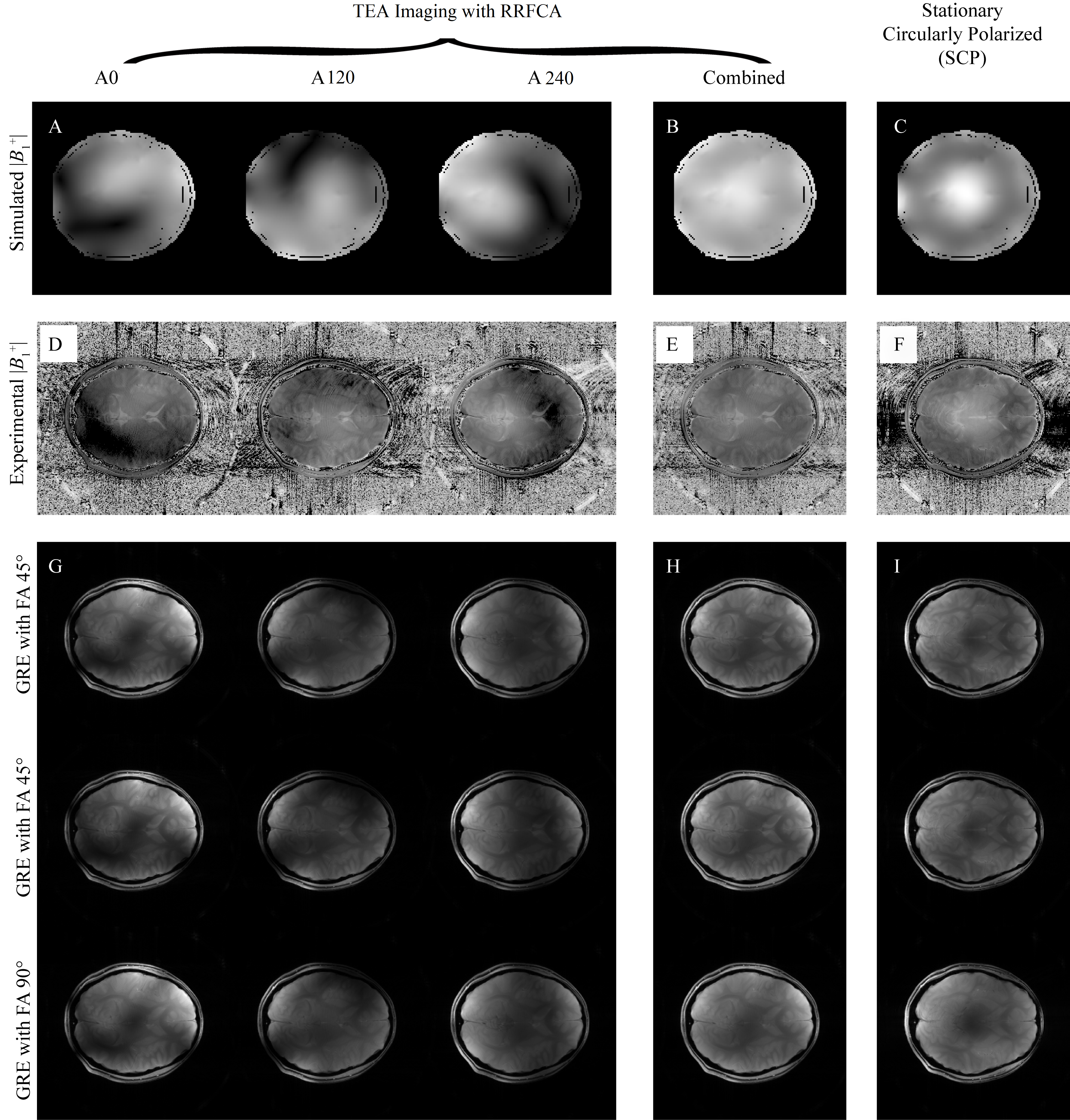
All experiments were performed on a 7T research system (Siemens Healthcare, Erlangen, Germany), equipped with an 8kW RF transmit channel. A prototype rotating array with 8 transceive elements was constructed (Fig.1). The rotary former with RF elements attached was placed into a stationary housing. The RF power was divided evenly using a custom 1-to-8 splitter as shown in the RF chain schematics in Fig.1. In transmission, although the RF elements were fixed to equal amplitudes relative phases can be achieved by adjusting the cable lengthes, providing phase-only RF shimming:$$B_1^+=\sum_{c=1}^Ce^{i\phi_c}B_{1,c}^+\hspace{35pt}[1]$$where coil channel index is denoted by subscript ‘c’.$$$\;\phi_c\;$$$is the phase delay of the c-th channel.Such a RF system configuration provides rudimentary pTx, without the capability of dynamic RF shimming. However, the goal is to achieve effective$$$\;B_1^+\;$$$profiles that are sufficiently uniform for different subjects, by finding a set of optimal $$$\;\phi_c\;$$$:$$[\phi_1,\phi_2,...,\phi_C]=argmin\frac{std(B_{1,effective}^+)}{mean(B_{1,effective}^+)}\hspace{35pt}[2]$$ $$where\; B_{1,effective}^+\approx B_{1,combined}^+ = \sum_{s=1}^S|\sum_{c=1}^Ce^{i\phi_cB_{1,c}^+}|_s\hspace{35pt}[3]$$'s' denotes the location index of the RRFCA. For easier evaluation of$$$\;B_{1,effective}^+\;$$$, it is substituted with $$$\;B_{1,combined}^+\;$$$as defined by the superposition of the magnitude$$$\;B_1^+\;$$$profiles of all the array positions. The Duke and Ella models from the Virtual Family$$$^8$$$ were used to represents varied subject geometries. The$$$\;B_1^+\;$$$fields derived from FDTD simulations were used to calculate channel-specific phases using Eq.[2]. In our experiments, the rotating array visited three azimuthal locations, denoted as A0°, A120° and A240°(Fig.2A). To keep the imaging time comparable to conventional arrays, only 1/3 of the k-space and the necessary auto-calibration signals (ACS) were acquired at each location, before moving onto the next locations.
In reception, each of the 8 elements was able to visit three unique locations, emulating 24 elements and unique sensitivity profiles with$$$\;\frac{360^{\circ}}{24}=15^{\circ}\;$$$between two nearby elements (Fig.2A right). The received signal was weighted by array location-dependent transmit sensitivities and individual receive sensitivities. Instead of trying to disentangle the transmit and receive sensitivities, they were absorbed into 24 composite sensitivities, assessed using a modified ESPIRiT$$$^9$$$ method directly from the 3 sets of ACS (Fig.2B). The time-multiplexed imaging and self-calibrated reconstruction are the main improvements compared with previous RRFCA approaches.$$$^{10-12}$$$
RESULTS
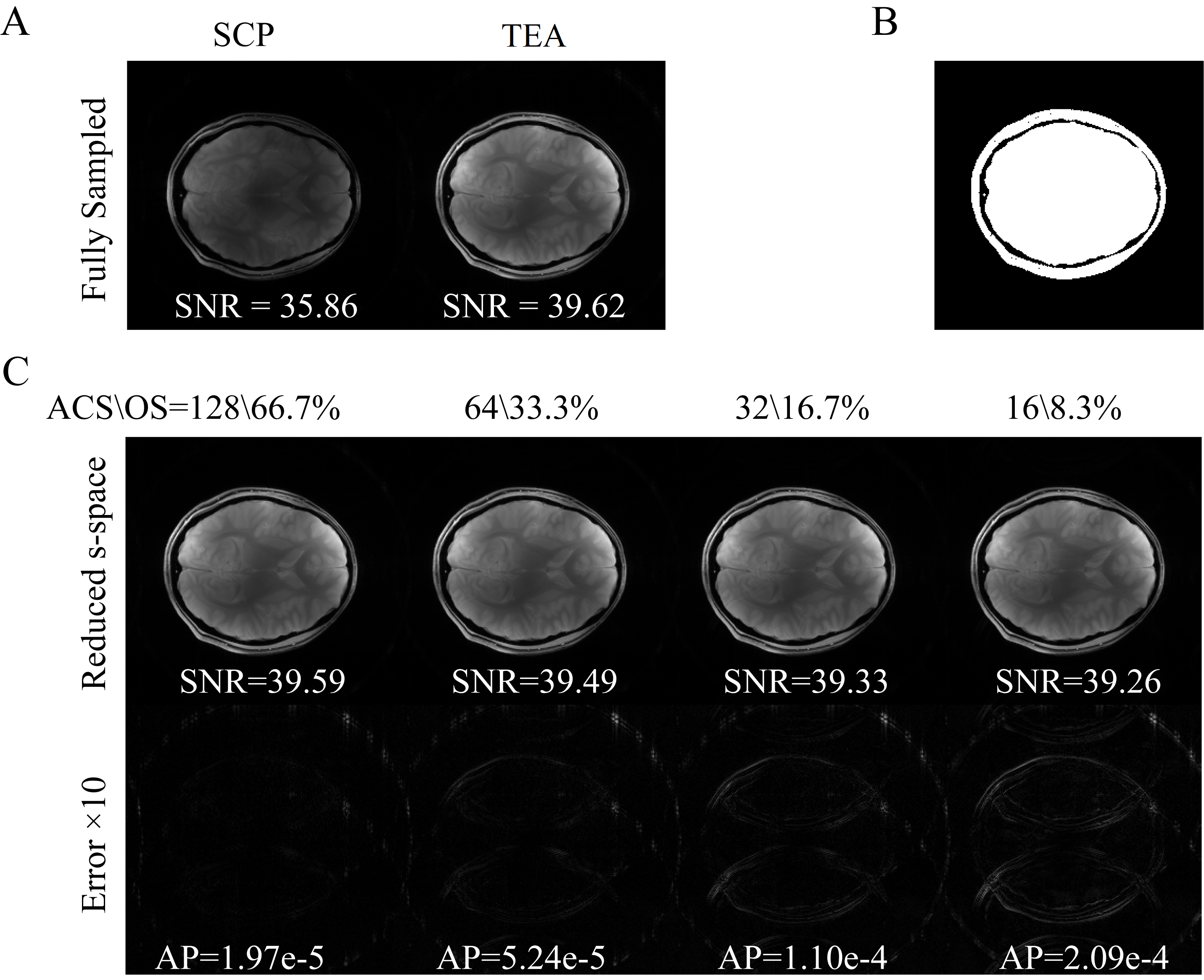
Experiment 1 - Excitation Homogeneity Comparison: Multi-slice gradient echo (GRE) imaging (TE/TR = 40/2000, FOV=300mm, Matrix=256×256, Slice=5mm) was performed on healthy volunteers with IRB approval. Both the stationary circularly polarized (SCP)-mode and the TEA mode were imaged with 45° and 90° flip-angles (FA), to estimate the flip-angle using the double angle method (DAM)$$$^{13}$$$, with the following relationship$$$\;FA=cos^{-1}(FA90/FA45/2)\;$$$The excitation homogeneity (h) was then calculated based on the derived FA distributions, using:$$$\;h=1-2{\frac{max(FA)-min(FA)}{max(FA)+min(FA)}}\;$$$A set of representative images can be seen in Fig.3, the simulated (Fig.3A) excitation profiles at individual locations match the measured (Fig.3D) profiles. Additionally, the individual profiles (Fig.3A and 3D) are complementary rather than uniform by themselves, and the effective excitation profiles by TEA-mode (Fig.3B and Fig.3E) were significantly more uniform than SCP-mode (Fig.3C and Fig.3F).Experiment 2 - SNR Comparison: The FA = 45° (FA45) sequences was repeated for the SCP and TEA modes for SNR assessment, using the dual acquisition subtraction method$$$^{14,15}$$$:$$$\;SNR=\sqrt{2}\frac{S_1}{SD_{1-2}}\;$$$where$$$\;S_1\;$$$is the mean signal intensity in the region of interest (ROI) of the first FA45 image; and$$$\;SD_{1-2}\;$$$is the standard deviation in the ROI of the difference between the first and second FA45 images; and the ROI was determined by applying a threshold on the first FA45 image. As can be seen in Fig.4, with full k-space sampling (equivalent to 200% over-sampling) the proposed TEA-mode (Fig.4A right) provides visibly stronger image intensity and noticeably higher SNR than SCP-mode (Fig.4A left). However, with 1/3 of the k-space at each coil location and decreasing ACS region, the SNR of TEA-mode didn't decrease significantly and remained significantly higher than SCP-mode (Fig.4C). Additionally, with decreasing calibration region, even with 16 calibration lines (over-sampling = 8.3%), the artifact power remained low.
DISCUSSION AND CONCLUSION
This work prototyped an 8-channel rotating RF array and the accompanying segmented imaging method for 7T for improved image quality. Instead of producing one uniform excitation throughout the imaging, multiple and complementary excitation profiles was produced in a time-multiplexed (segmented) fashion, providing excitation homogeneity across the segments. The rotating also provided additional unique receive sensitivity profiles, capable of enhanced image SNR with proper reconstruction.Acknowledgements
This work was supported in part by the Chinese National Major Scientific Equipmemt R&D Project (Grant No. ZDYZ2010-2)References
1. Pauly J, Nishimura D, Macovski A. A k-space analysis of small-tip-angle excitation. Journal of Magnetic Resonance 1989;81(1):43-56.
2. Pauly J, Nishimura D, Macovski A. A linear class of large-tip-angle selective excitation pulses. Journal of Magnetic Resonance (1969) 1989;82(3):571-587.
3. Katscher U, Bornert P, Leussler C, van den Brink JS. Transmit SENSE. Magnetic Resonance in Medicine 2003;49(1):144-150.
4. Zhu Y. Parallel excitation with an array of transmit coils. Magnetic Resonance in Medicine 2004;51(4):775-784.
5. Grissom W, Yip CY, Zhang ZH, Stenger VA, Fessler JA, Noll DC. Spatial domain method for the design of RF pulses in multicoil parallel excitation. Magnetic Resonance in Medicine 2006;56(3):620-629.
6. Ibrahim TS, Lee R, Baertlein BA, Abduljalil AM, Zhu H, Robitaille P-ML. Effect of RF coil excitation on field inhomogeneity at ultra high fields: a field optimized TEM resonator. Magnetic Resonance Imaging 2001;19(10):1339-1347.
7. Mao W, Smith MB, Collins CM. Exploring the limits of RF shimming for high-field MRI of the human head. Magnetic Resonance in Medicine 2006;56(4):918-922.
8. Andreas C, Wolfgang K, Eckhart GH, Katharina H, Marcel Z, Esra N, Wolfgang R, Rolf J, Werner B, Ji C and others. The Virtual Family—development of surface-based anatomical models of two adults and two children for dosimetric simulations. Physics in Medicine and Biology 2010;55(2):N23.
9. Uecker M, Lai P, Murphy MJ, Virtue P, Elad M, Pauly JM, Vasanawala SS, Lustig M. ESPIRiT—an eigenvalue approach to autocalibrating parallel MRI: Where SENSE meets GRAPPA. Magnetic Resonance in Medicine 2014;71(3):990-1001.
10. J. Jin, Liu F., Trakic A., Weber E., Crozier S., "Application of Rotating RF Coil Array in B1 Shimming with Strict Local SAR Constraints," in ISMRM (International Society for Magnetic Resonance in Medicine), Salt Lake City, USA, 2013.
11. M. Li et al., "Highly accelerated acquisition and homogeneous image reconstruction with rotating RF coil array at 7T-A phantom based study," (in eng), J Magn Reson, vol. 240, pp. 102-12, Mar 2014.
12. M. Li et al., "In vivo sensitivity estimation and imaging acceleration with rotating RF coil arrays at 7 Tesla," (in eng), J Magn Reson, vol. 252, pp. 29-40, Mar 2015.
13. Insko EK, Bolinger L. Mapping of the radiofrequency field. Journal of Magnetic Resonance, Series A 1993;103(1):82-85.
14. Wen H, Denison TJ, Singerman RW, Balaban RS. The Intrinsic Signal-to-Noise Ratio in Human Cardiac Imaging at 1.5, 3, and 4 T. Journal of Magnetic Resonance 1997;125(1):65-71.
15. Firbank MJ, Coulthard A, Harrison RM, Williams ED. A comparison of two methods for measuring the signal to noise ratio on MR images. Physics in Medicine and Biology 1999;44(12):N261.
Figures