1272
Triggered software defined radio for parallel transmission MRI research1Physical Sciences, Sunnybrook Research Institute, Toronto, ON, Canada, 2Department of Medical Biophysics, University of Toronto, Toronto, ON, Canada
Synopsis
Building a flexible setup for parallel transmission (PTx) MRI research is still challenging. A commercial software defined radio device was tested for suitability in a revised setup. Software was developed to make the device generate radiofrequency (RF) bursts in response to triggers. Preliminary bench tests showed quick and reliable triggering, consistent amplitude and phase across channels, and successful runtime adjustment. An initial PTx MRI demonstration showed capability for RF shimming in echo planar imaging of a phantom. Further troubleshooting is planned to reduce observed phase jitter, but the setup is already capable of a range of PTx research applications.
Introduction
Parallel transmission (PTx) applies radiofrequency (RF) power via multiple independent transmission channels. PTx is becoming increasingly important for MRI,1 and optimization of PTx is the subject of much research. Software-defined radio (SDR), which substitutes a host computer system for dedicated RF electronics, has been explored as a flexible, lower-cost alternative for research into MRI2 and PTx.3In the present work, an off-the-shelf SDR device was integrated into an existing PTx research setup that substitutes for an MRI system’s transmission chain in a modular manner,4 leveraging the original receiver chain, pulse sequences, etc. While a previous iteration had latency and potential noise amplification from processing the MRI system’s transmissions,3 the new setup should avoid those issues and provide greater flexibility by using newly generated RF transmissions. The SDR system was characterized on the bench and then connected to a commercial 3‑T MRI system for an initial demonstration of PTx RF shimming capability.
Methods
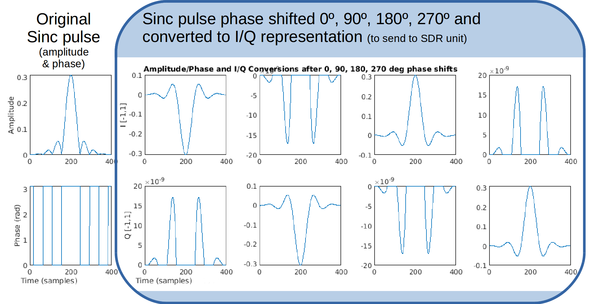
For a 4-channel prototype, one 4-channel Tx/Rx SDR unit (Crimson TNG, Per Vices Corp.) was controlled by a desktop computer (4-core Intel i5-2500, Ubuntu Linux 16.04). Based on open-source sample code, a C++ program configured the SDR unit to respond to triggers by transmitting RF bursts. Unlike the previous iteration of this setup which streamed data continuously between the SDR unit and host computer, triggers were handled internally by the SDR unit, ensuring minimal latency and phase coherence between channels. The software on the desktop computer continuously maintained a queue of RF samples to be transmitted with each trigger. Four independent sets of amplitude and phase data describing RF pulses were initially read from a text file (Fig.1). Further runtime amplitude and phase adjustments were applied separately to each channel, then the samples were formatted and sent over 10-Gb network links. For preliminary bench testing, an arbitrary function generator (AFG3102, Tektronix) supplied triggers, and SDR outputs were recorded using an oscilloscope (DSO-X 3034A, Agilent Technologies).The SDR system was then connected to a 3‑T MRI system (Prisma, Siemens Healthineers) via a custom coil plug.4 The MRI system’s RF transmissions were discarded in a load, and SDR was used instead to generate new transmissions for PTx. Synchronization was achieved by connecting to the MRI system’s 10-MHz clock, and the RF unblank signal was used to trigger the SDR unit via a custom optical-to-electrical convertor. As an initial demonstration, a sphere phantom was imaged in a custom Tx/Rx coil array, with the SDR unit generating a sinc pulse to simulate the unmodified MRI system’s RF transmission during echo planar imaging (EPI).
Results
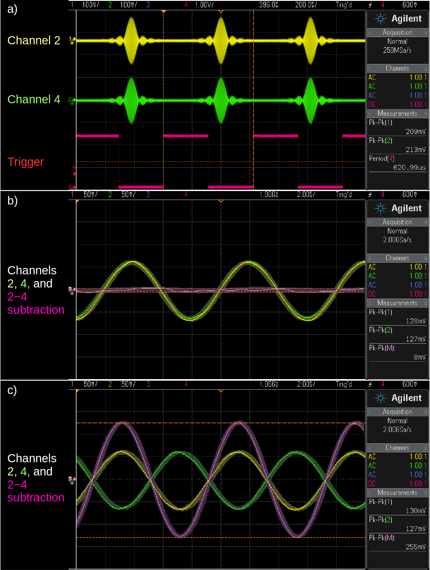
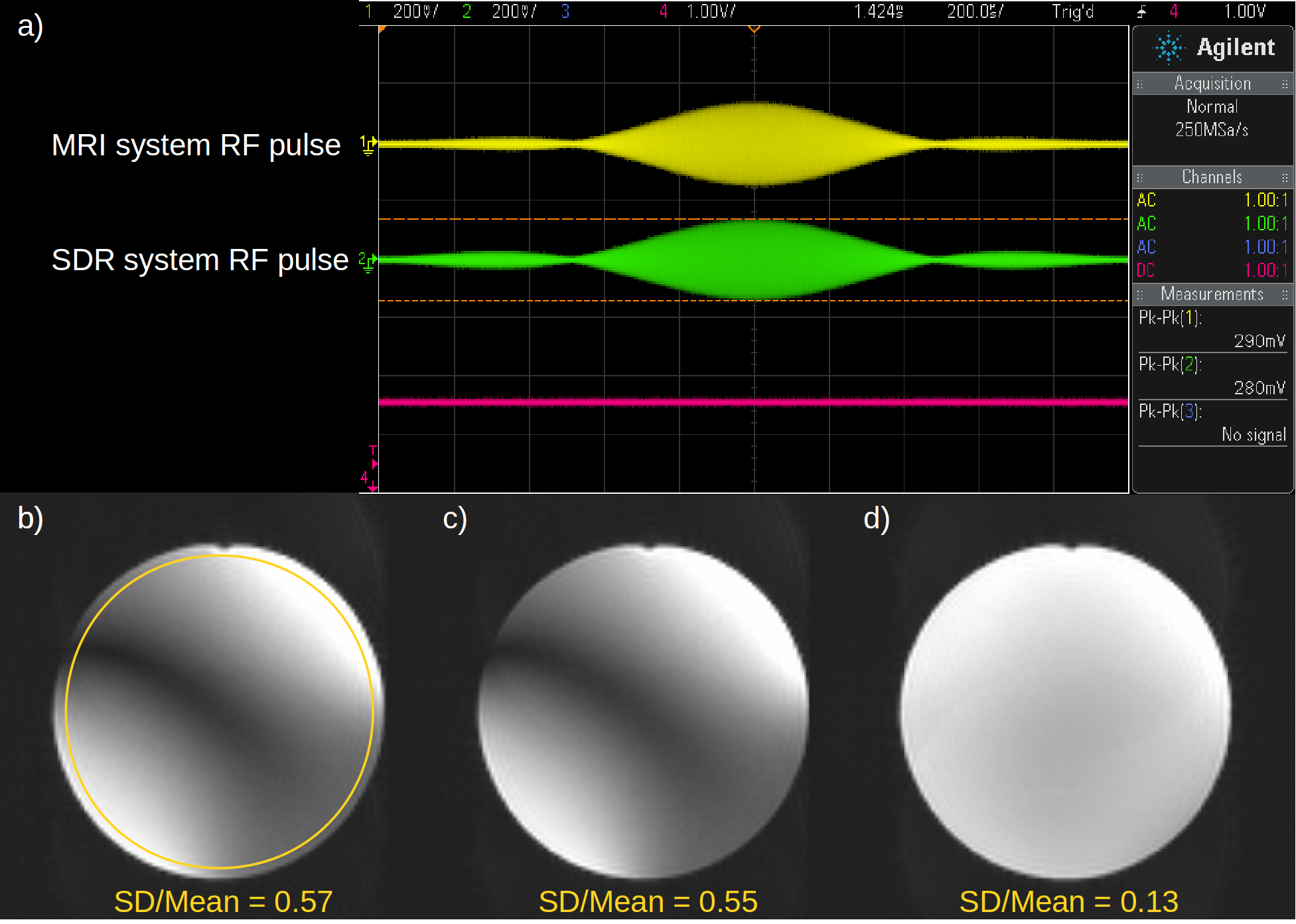
During bench testing, the overall pulse envelope was consistent across channels (Fig.2a), with a 66-μs sampling rate-dependent trigger delay at 200 kS/s. Triggering occurred reliably during stress testing with a trigger interval of 621 μs, using a short (625μs) sinc pulse similar to one used during prescan frequency adjustment on the MRI system (Fig.2a). Just 47 % of one host CPU and 3.8 MB/s network bandwidth were occupied during the stress test. Phase and amplitude were coherent across channels and successfully manipulated (Fig.2b-c), but some phase jitter with a range of ±0.24 ns was visible from burst to burst, associated with the alignment of the system clocks and the triggers from the function generator. During 4-channel PTx MRI, the SDR output closely matched the MRI system’s own RF transmissions (Fig.3a). The resulting image without phase shifts across PTx channels (Fig.3c) was nearly identical to using the MRI system’s transmissions (Fig.3b), and simply applying quadrature phase shifts with the SDR setup improved image uniformity dramatically (Fig.3d): A variation metric (SD/Mean) dropped from 0.55 to 0.13 across the large region of interest (Fig.3b).Discussion
Bench testing showed good performance, with consistent amplitude and phase coherence across channels, as required for PTx MRI. The trigger delay was short enough to fit in the settling time between the RF unblank onset and the RF pulse, and a trigger interval as short as the RF pulse itself could be sustained. Thus, even for a fast EPI sequence, this setup should permit direct substitution in the unmodified sequence if the new pulse is similar in length to the original, as in RF shimming. Troubleshooting is underway to ensure clock and trigger alignment for less phase jitter, but the imaging results show that the system is already acceptable for initial research applications. For example, although the current software interface only supports static RF shim settings, amplitude and phase adjustments were applied during runtime, making it possible to study dynamic RF shimming. The software also supports independent specification of pulses in each channel, required for methods like Transmit SENSE.5 Finally, the initial software uses little CPU and network resources in this triggered burst mode, leaving ample resources for expansion to higher PTx channel counts and possibly realtime feedback via SDR receiver channels also available on this SDR device.Conclusion
An off-the-shelf SDR system operating in triggered burst mode was tested in a setup for PTx MRI research. Initial bench testing and MRI demonstrated good performance. Additional development is required to improve remaining timing limitations, but the system already seems capable of investigating a range of PTx applications.Acknowledgements
Thanks to the Canada Foundation for Innovation for funding, and to Pei-Shan Wei for the lovely sinc pulse and helpful talk.References
1. Padormo F, Beqiri A, Hajnal JV, Malik SJ. Parallel transmission for ultrahigh-field imaging. NMR Biomed. 2016; 29: 1145-1161.
2. Hasselwander CJ, Cao Z, Grissom WA. gr-MRI: A software package for magnetic resonance imaging using software defined radios. J Magn Reson. 2016; 270: 47-55.
3. Tam F, Yang B, Graham SJ. Software defined radio-based platform for parallel transmission MRI research. Proc Intl Soc Magn Reson Med. 2018; 27: 1690.
4. Yang B, Wei PS, McElcheran CE, Tam F, Graham SJ. A platform for 4-channel parallel transmission at 3T: Demonstration of reduced radiofrequency heating in a test object containing an implanted wire. J Med Biol Eng. 2019; 39: 835.
5. Katscher U, Börnert P, Leussler C, van den Brink JS. Transmit SENSE. Magn Reson Med. 2003; 49: 144–150.
Figures