1269
Retrospective Electromagnetic interference mitigation in a portable low field MRI system1Athinoula A Martinos Center for Biomedical Imaging, Charlestown, MA, United States, 2Harvard Medical School, Boston, MA, United States, 3Dept. of Electrical Engineering, Massachusetts Institute of Technology, Cambridge, MA, United States, 4Harvard-MIT Division of Health Sciences and Technology, Cambridge, MA, United States
Synopsis
The performance of a low field Point of Care (POC) MRI system operating outside an RF shielded room is adversely affected by the presence of electromagnetic interference signals, which produce image artifacts, sometimes complicated enough to be confused with image noise. We demonstrate a post-processing interference suppression technique using an external reference coil and dynamically updated transfer function to detect the interference and remove it from the imaging data.
Introduction
Electromagnetic Interference (EMI) contaminates MR signals and decreases the diagnostic quality of the image. These nuisance signals are detected the same way as the spins, i.e. through Faraday detection with primary MR imaging coils. Conventional MRI scanners use RF shielded enclosures to reduce EMI. Specialized low field, portable point of care (POC) MRIs have the advantage of being low-cost, lightweight and mobile and could extend the use of MRI to unconventional locations. However, the necessity of an RF shielded room renders the system non-portable and precludes their use in a POC setting. To address this problem, we use a pickup coil external to the imaging volume to detect interference, a method previously demonstrated 1,6. We then employ a dynamic transfer function calculation (updated shot to shot) in order to detect EMI which is correlated to the EMI picked up by the primary imaging coil and remove it in postprocessing from the primary MR data.Methods
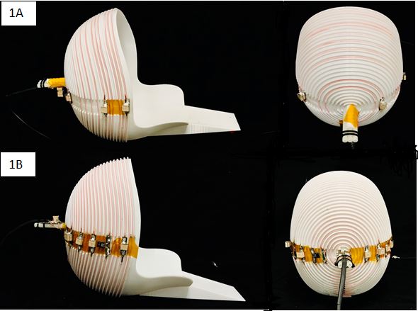
We validated the interference mitigation strategy in a portable low-field system (80mT) for human brain imaging 2-5. The system uses a 122kg permanent magnet Halbach cylinder that was designed to fit compactly around the head and have a built-in readout gradient. The Halbach magnet is passively shielded with ~100um thick copper foil wrapped around the cylinder to reduce RF interference. Although there is a large gap in the shield for the bore opening, the passive shielding is adequate for imaging phantoms contained within the magnet. However, when imaging human subjects, the body extending outside of the passively shielded environment acts like an antenna and “pipes” nuisance signals to the imaging coil. Our method supplements the passive shielding around the magnet with an external detector to record EMI and retrospectively remove it from the imaging data.We used a spiral helmet solenoid-like coil7 with 12 turns (Fig 1a) as the imaging coil with a 50 ohm 37db gain pre-amplifier (MITEQ P/N AU 1583) and 24 dB second stage amplifier (Mini-circuits ZHL-500LN+). The external interference pickup coil is also a spiral coil tuned to the Larmor frequency (3.38MHz) with 30 turns(fig 1b) and a Mini-circuits ZHL-500LN+ pre-amplifier. In each acquisition window of the RARE sequence, the external coil samples “noise data” simultaneously with the primary coil’s echo acquisition. In addition, we sample 2.56 ms of “noise” from both coils at the end of each echo train, 23 times. The latter data dynamically model the relationship (transfer function) between signals measured by the 2 coils and generate a new transfer function for each TR in the sequence to account for environmental changes during the sequence. Assuming CpriN to be the FFT of the primary coil calibration data, where N is the number of acquisition points, and CextN to be the FFT of the external coil calibration data, the transfer function is HN = CpriN / CextN for each TR, providing the gain and phase relationship for every frequency bin in the bandwidth. Defining SpriN and SextN as the primary coil MR data and the “noise data” acquired from the external coil during the echo train, SpriN - HN x SextN gives the EMI mitigated imaging data.
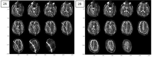
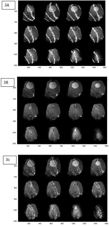
To demonstrate the method, we applied a 3.38MHz sine wave signal to a nearby antenna as an EMI source and acquired a T2-weighted image 3D RARE images. The in vivo results shown in Figure 2 were acquired in 4 min using a TR/TEeff of 2.54s/167ms with 23 PEs in X and 97 PEs in Z, yielding an image resolution of ~2x2x7mm. To test the effectiveness of the algorithm in the presence of a less coherent EMI source, we also used a stepper motor as an EMI source during imaging of an anthropomorphic head phantom.
Results and Discussion
fig 2 shows the uncorrected and corrected in vivo images with a coherent interference source at a single frequency (interference line follows the non-linear gradient iso-contour). fig 3 shows the corresponding correction for the stepper motor. While the correction with the incoherent source is not as effective, the improvement is significant. We also demonstrate the value of using dynamic calibration data from each TR of the sequence. Fig 3 shows the value of using dynamic calibration data by comparing to a single transfer function resulting in poorer artifact mitigation than in fig.2.Conclusion and Future work
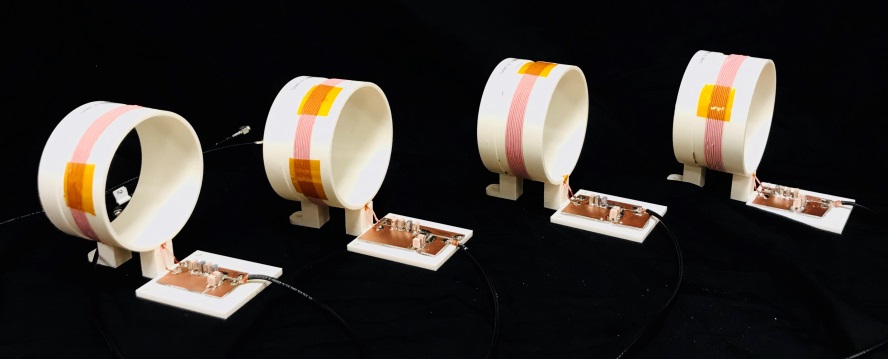
We demonstrate a proof-of-concept EMI correction method using a single external pick-up coil. Future work will extend this to use multi-coil measurements for increased accuracy in the EMI cancellation using the coils in fig 4. Another goal will be replacing the external pick-up coils with electrodes or surface coils on the body (but outside the magnet) to more directly probe nuisance signals “piped” up from the body.Acknowledgements
We would like to thank Monika Śliwiak for her contributions especially in 3D printing design and Matt Rosen and Neha Koonjoo for assistance with the spiral head coil. Funding from NIH NIBIB R01EB018976 and 5T32EB1680.References
1. Rearick Todd et al., “Noise Suppression methods and apparatus”. Patent no. WO2016037028. 2017.
2. C. Z. Cooley et al., “Two-dimensional imaging in a lightweight portable MRI scanner without gradient coils,” Magn. Reson. Med., vol. 73, no. 2, pp. 872–883, Feb. 2015.
3. C. Z. Cooley et al., “Design of Sparse Halbach Magnet Arrays for Portable MRI Using a Genetic Algorithm,” IEEE Trans. Magn., vol. 54, no. 1, pp. 1–12, Jan. 2018.
4. P. McDaniel, C. Z. Cooley, J. P. Stockmann, and L. L. Wald, “3D imaging with a portable MRI scanner using an optimized rotating magnet and gradient coil,” Proc. 26th Annu. Meet. ISMRM Paris 2018, p. 0029, 2018.
5. P. McDaniel, C. Z. Cooley, J. P. Stockmann, and L. L. Wald, “A target-field shimming approach for improving the encoding performance of a lightweight Halbach magnet for portable brain MRI,” Proc. 27th Annu. Meet. ISMRM Montr. 2019, p. 0215, 2019.
6. Patz Samuel et al.,” Systems and methods for portable magnetic resonance measurements of lung properties”. Patent no: WO2013016639. 2013.
7. LaPierre Cristen et al., “A single channel spiral volume coil for in vivo imaging of the whole human brain at 6.5 mT”.Proc. 23rd Annu. Meet ISMRM Toronto.2015, p. 1793,2015.
Figures