1267
A deflectable positionally-localized Virtual Biopsy “Gun”: Construct and initial testing1Medicine (Cardiology), The Johns Hopkins University, Baltimore, MD, United States, 2Radiation Oncology, Johns Hopkins University, Baltimore, MD, United States, 3Mechanical Engineering, University of Arkansas, Fayetteville, AR, United States, 4Radiology, Brigham and Womens Hospital, Boston, MA, United States, 5Medicine (Cardiology), Johns Hopkins University, Baltimore, MD, United States, 6MRI, Siemens Healthineers, Boston, MA, United States
Synopsis
Evaluating tissue properties prior-to or during therapy, such as locating cancerous and necrotic cells, or characterizing response to radiation or ablation, is conventionally performed by tissue excision, followed by pathologic examination. An alternative is diagnosing tissue in-situ without removing it, as performed using Optical-Coherence-Tomography or Intra-Vascular-UltraSound. We aim to perform tissue definition in soft-tissues not accessed through body-orifices or blood-vessels by combining; (1) Steerable tissue-puncture, (2) MR-Tracking-motion-localization, and (3) imaging along the punctured-holes' walls. Utilization requires rapid high-CNR multiple-contrast MRI. A deflectable virtual-biopsy “gun” for diagnosing cervical-cancer radiation-therapy response was developed. It imaged ~15mm surrounding punctured-holes created for brachytherapy seed-delivery.
Introduction
High-Dose-Rate brachytherapy of cervical cancer is performed after external beam radiation therapy (EBRT), aiming to kill residual tumor-cells that survived EBRT by providing more-focused higher-dose radiation. Procedures commonly require implantation of 10-20 “needles” into residual-tumor regions. It is important to (I) determine exactly where the residual tumors are, and (II) deliver the correct radiation to them, since surviving cells may survive some level of radiation dose, while excessive dose may harm neighboring tissues. HDR brachytherapy treatments (“fractions”) are commonly delivered each 6 hours over a 48-hour period. Today, non-invasive (e.g. surface-coil based) MRI imaging is widely performed prior to cervical-cancer brachytherapy-needle placement (1), and MR-Tracked (MRT) active-needle placement is performed at two hospitals (2), at ~15-min procedure speeds that rival ultrasound-guided needle placement (2,3). We envision increased MR utilization, where (i) combined MRT and high-speed MRI, in tissues surrounding the punctures, would be performed during needle placement in order to determine more precisely, along the needle’s trajectory, where residual tumor or, alternatively, fibrotic tissue and post-radiation inflammation exists, as well as the degree of tissue hypoxia, which gages the dose requirements, and (ii) similar procedures could be performed between fractions to determine if therapy should be altered.Extended MRI use will require (a) fast MRI procedures, so as not to excessively extend the procedures, and (b) high-resolution and high Contrast-to-Noise-Ratio per unit time (CNR/t) imaging of the desired tissue attributes. We attempted to provide (a, b) by using miniature MRI arrays that can be brought very close to the tissues of interest using the same holes made for radiation-seed implantation, with the imaging probes penetrating into the tissues to a depth which extends beyond the torn, highly-perturbed, tissue that immediately surround the puncture hole. Exemplary MRI contrasts that are employed in radiation-therapy follow-up include: Hypoxia imaging with T2* GRE (4), Fibrosis imaging with UTE/Short Inversion-Time-UTE (5,6), and metabolism with multiple-delay-time Contrast-Enhanced 3D-GRE and DWI (7).
Herein we focus on device construction and initial testing. Workflow and sequence-specific CNR/t issues will be addressed later.
Methods
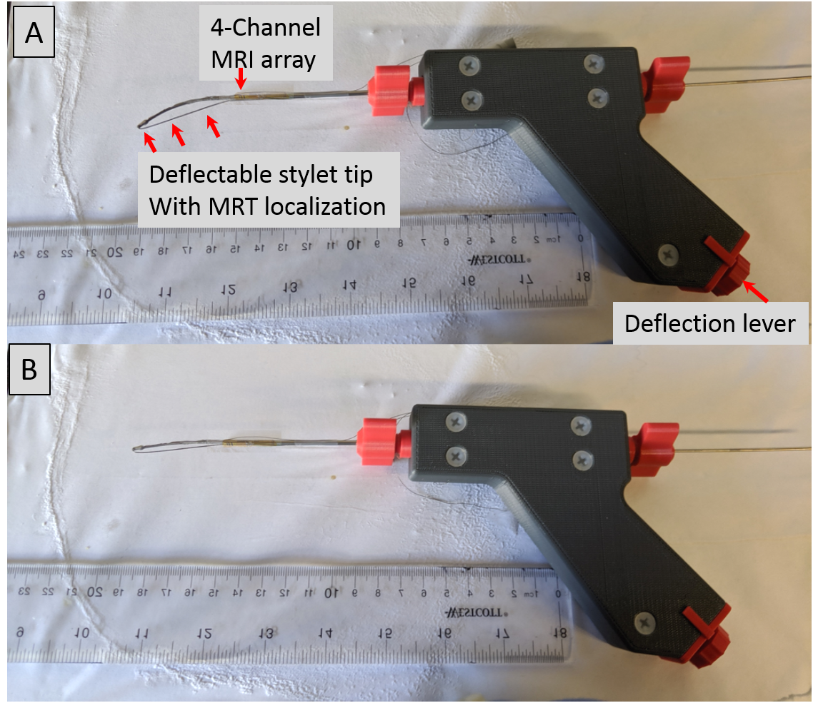
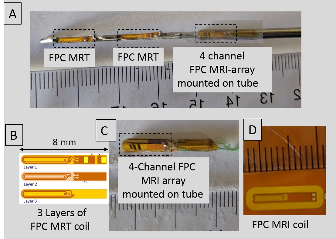
The Virtual Biopsy “Gun” [Figures 1, 2]: A (1.4mm outer-diameter 330mm length) flexible nitinol stylet, developed for MR-guided brachytherapy (ref), was instrumented with a nitinol pull-wire. The tip location & orientation was provided at 0.8x0.8x0.8 mm3 resolution and 15 frames-per-second rate, using two MR-Tracking (MRT) microcoils (3-layer flexible-printed-circuit (FPC) antennas; Length:Width:Thickness=8mm:1.1mm:0.2mm, with embedded capacitors providing 63.8 MHz tuning and matching) placed in groves along the shaft. A 2.2mm OD nitinol tube was positioned so that its distal end lay 12mm behind the proximal MRT coil. The distal tube was mounted with a 4-coil array of tuned and matched miniature (2-layer FPC antennas; Length:Width:Thickness=14mm:1.8mm:0.2mm) imaging coils, arranged at 90-degree increments on its circumference. A 0.2mm mylar layer between the imaging-coils and the nitinol-tube increased the RF-lobe's outward projection, with image-magnetic-fields from the metallic-tube reinforcing the main field (8). Signals from the tracking and imaging coils were conducted on 44 AWG micro-coaxial cables to the gun, converted to larger coaxial cables, and sent to an 8-channel MRI receiver (3).Inspired by the concentric tube robot design (9), the virtual biopsy “gun” was designed using an actively deflectable inner stylet and an outer tube [Figure 1]. Stylet tip deflection (maximum:450,without-resistance) was precisely controlled by pull-wire tension, and activated by a rotary lever at the gun’s base. The gun could thereby control the depth of penetration, and the puncture direction, bringing the trajectory back to the clinician’s desired path by correcting for needle deflections resulting from the pelvic tissue’s muscular composition.
Mechanical Deflection: Tested in ex-vivo muscular bovine tissue. The degree of path deflection possible during perforation of the beef sample was tested, with simultaneous MRT tracking of the changes enabling quantification of the actual deflection angles during maximum pull-wire tension.
Phantom SNR Imaging: Imaging was performed with the 4-channel array in a 30cm FOV saline phantom, with the stylet tip located at the phantom's center in the Anterior-Posterior direction, and the scanner's body array and spine arrays located Anterior and Posterior, respectively. A 2D GRE sequence, TR/TE/flip=30ms/5ms/150 was employed in order to compare the array's SNR with that of the 1.5T Siemens Aera scanner's spine array at various distances from the nitinol tube surface.
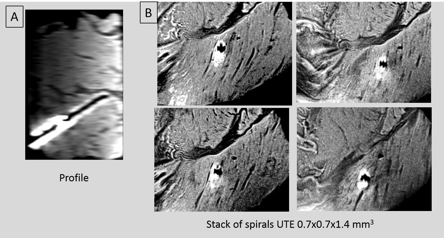
Ex-vivo Imaging: Performed in bovine shoulder tissue. Stacks of-Spirals UTE (TR/TE/θ=20ms/60us/10o, 0.7x0.7x1.4mm3,60sl/3:13min).Spine array and 4-ch array employed.
Results
Mechanical Deflection: MRT tracking of the path changes in the bovine sample detected changes of 45 and 30 degrees in tip trajectory at penetration depths of 120 and 200 mm, respectively.Phantom Imaging: The 4-channel array provided an SNR enhancement of 10-11x and 7-8x, at distances of 6mm and 10mm from the tube surface, respectively, relative to the spine array.
Ex-vivo Imaging: [Figure 3]. High-resolution UTE images showed fine details at the puncture walls. The 4-channel-array imaging region is ~15x15x60mm3 (enlarged due to inductive coupling).
Conclusions
The virtual biopsy gun enabled steering brachytherapy trajectories and high SNR imaging of the punctured- holes' walls, validating that puncture-walls imaging can be performed in reasonable scan times. Further experiments will explore the gun's effectiveness, along with specific sequences, to quantify acute changes in tissue properties due to radiation injury.Acknowledgements
R01-HL094610, R01-HL126092, R21-CA167800References
(1) Chargari C, Deutsch E, Blanchard P, Gouy S, Martelli H, Guérin F, Dumas I, Bossi A, Morice P, Viswanathan AN, Haie-Meder C. Brachytherapy: An overview for clinicians. CA Cancer J Clin. 2019; 69:386-40
(2) de Arcos J, Schmidt EJ, Wang W, Tokuda J, Vij K, Seethamraju RT, Damato AL, Dumoulin CL, Cormack RA, Viswanathan AN. Prospective Clinical Implementation of a Novel Magnetic Resonance Tracking Device for Real-Time Brachytherapy Catheter Positioning. Int J Radiat Oncol Biol Phys. 2017;99(3):618-626.
(3)Morcos M, Lee J, Schmidt EJ, Viswanathan AN. Reduced implant times and improved needle placement with real-time active MR-tracking of interstitial needles. Proceedings of European Society for Radiotherapy (ESTRO) 2020
(4) Höckel M, Kahn T, Einenkel J, Manthey N, Braumann U-D, Hildebrandt G, Leo C, Hentschel B, Vaupel P, Horn L-C. Local spread of cervical cancer revisited: A clinical and pathological pattern analysis.Gynecologic Oncology 2010; 117: 401–408
(5) Ramadeen A, Hu X, Morikawa L, Zhang L, Lau JYC, Liu G, Pop M, Connelly KA, Dorian P, Wright GA. Characterization of the ultrashort‐TE (UTE) MR collagen signal, NMR in Biomedicine 2105;28: 1236-1244
(6) Schmidt EJ, Muradyan I, Benkert T, Bhat H, Kolandaivelu A, Halperin HR, N. Viswanathan AN. Imaging wound-healing-related fibrosis using Short Inversion Time Ultra-Short TE (STIR-UTE), Proceeding ISMRM 2019.
(7) Jalaguier-Coudray A, Villard-Mahjoub R, Delouche A, Delarbre B, Lambaudie E, Houvenaeghel G, Minsat M, Tallet A, Sabatier R, Thomassin-Naggara I. Value of Dynamic Contrast-enhanced and Diffusion-weighted MR Imaging in the Detection of Pathologic Complete Response in Cervical Cancer after Neoadjuvant Therapy: A Retrospective Observational Study. Radiology 2017;284:432-442
(8) Alipour A, Meyer ES, Elahi H, Fink S, Halperin HR, Viswanathan AN, Schmidt EJ. Cervical-Cancer Imaging for brachytherapy planning employing an endo-vaginal array that includes an enhanced forward-looking coil. Proceedings ISMRM 2019
(9) Chen Y, Poorman ME, Comber DB, Pitt B, Liu C, Godage IS, Yu H, Grissom WA, Barth EJ, Webster RJ. Treating epilepsy via thermal ablation: initial experiments with an MRI-guided concentric tube robot. In Design of Medical Devices Conference. American Society of Mechanical Engineers Digital Collection 2017.
Figures