1266
Single-sided magnet design for an MR guided lumbar puncture (LP) device1Athinoula A Martinos Center for Biomedical Imaging, Dept. of Radiology, Massachusetts General Hospital, Charlestown, MA, United States, 2Harvard Medical School, Boston, MA, United States, 3Dept. of Electrical Engineering, Massachusetts Institute of Technology, Cambridge, MA, United States, 4Dept. of Neurology, Massachusetts General Hospital, Boston, MA, United States, 5Harvard-MIT Division of Health Sciences and Technology, Cambridge, MA, United States
Synopsis
Lumbar Punctures (LP) are generally guided by palpation only without visualization of the internal anatomy, leading to repeat attempts and/or avoidance in difficult cases. Image guidance with US and X-ray is possible, but US has poor depth and CSF contrast and radiation from X-ray complicates Point of Care (POC) use. We present a magnet design for a POC MR guided LP device that will couple to a mechanical track for needle insertion. The single-sided magnet is an NdFeB array and achieves a 40mT field and ~50mT/m built-in gradient in the ROI. Simulations of the magnet and imaging procedure are presented.
Introduction
In this work, we simulate the feasibility of a light-weight single-sided MR device that can pre-image the relevant anatomy needed to guide lumbar puncture (LP) in a point-of-care (POC) setting. Our goal is to reduce barriers to performing this important diagnostic and drug delivery procedure outside central hospital settings, expanding its availability to a broader range of healthcare locations and increasingly inexpert staff. While already routinely used to diagnose several conditions, the need for routine LP is poised to dramatically expand in the diagnosis of Alzheimer’s Disease1-5 where protein CSF biomarkers accessed through LP have emerged as a premiere diagnostic tool for predicting future progression. LP is also expected to see increasing use for CNS delivery of gene editing therapies and drugs that have poor blood brain barrier penetration6.Although routinely performed, LP is conventionally guided by palpation without visualization of the internal anatomy. This leads to clinician anxiety and avoidance and repeated puncture attempts in difficult cases7. Ultrasound and x-ray have been used to guide LP, but both have significant shortcomings. Ultrasound imaging cannot see the CSF target and the ionizing nature of x rays is difficult to manage in routine POC use. In contrast, our proposed MR-guided LP device could both streamline LP within a hospital and enable it to be performed outside central hospital settings or by inexpert staff.
Our proposed device integrates a lightweight (<25kg) device for MRI of the spine and surrounding tissues with mechanically-constrained 22-gauge needle insertion, thereby guaranteeing registration between the image and needle path without requiring real-time imaging of the needle (Fig. 1). During use, the practitioner positions the MR-guidance device’s central ~2cm diameter needle insertion hole over the standard needle entry mark between L4 and L5 (Figure 1). Next, a set of anatomical T2 weighted images is acquired, on which the expected path of the needle is plotted. Based on the image plan, a mechanical needle guidance track is set to the planned path avoiding vertebrae and any calcifications in the ligamentum flavum. The maximum depth is planned to just enter the T2-bright subarachnoid space. With the angulation and depth-stop set, the practitioner manually pushes the needle in along this track.
Methods
We optimize and simulate a magnet array consisting of N=248 N52-NdFeB magnets arranged in two layers in concentric rings and arcs (Fig. 2). Individual magnet blocks are all 25.4x[y]x25.4mm3 where the [y]-dimensions were numerically optimized in a continuous range of 0-25.4mm. The magnet was designed with symmetry about the XY and XZ planes to produce an x-oriented B0 field gradient (ie into the patient’s back).The sizes and angular orientations of the magnet blocks were optimized to produce a 4x6x8 cm3 homogeneous magnetic field along the spine at a depth of 8cm from the magnet surface and overlaying the adult L3-L5 spine (Fig. 1). The optimization was performed with the Matlab fmincon tool with: cost function – range of B0 magnitude (fcost=range{|B0|}), computed at points on a 1cm3 grid within the ROI; constraints - mean |B0| >= 40mT, 0<=y<=25.4mm. Magnet blocks were modeled as L=5 multipole field sources for field computation during optimization. Simulated B0 maps for the optimized design were computed using BiotSavart simulation software (Ripplon).
The magnet is designed to acquire a ~3 minute duration 3D RARE spin-echo image with the Gx ~ 50mT/m built-in read-out gradient, Gy phase encoding along the echo-train, and Gz phase encoding shot-to-shot. A 2D imaging simulation was performed using the XZ field-map shown in Fig. 3 for Gx and a linear planar gradient coil producing Gz = 8mT/m peak for the Z phase encode. The simulation FOV is 4cm x 8cm, with 256 readout points, BW = 50KHz, and 97 phase-encodes in Z.
Results
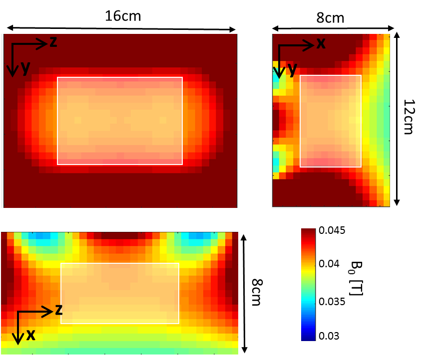
Figure 2 shows the preliminary magnet design for the single-side LP device with the simulated B0 field shown as 0.5mT iso-contours. The resulting magnet measures 8x42x50 cm3, contains 24.2kg of rare-earth material, and produces a mean field of 40.9mT in the target ROI. Figure 3 shows the simulated magnetic field-maps in the 3 cartesian planes with white boxes indicating the target ROI. We note that this initial design is only preliminary since some magnet blocks intersect and the needle gap may be too small; issues requiring added constraints to the optimization procedure.Figure 4 shows the image simulation results. The simulation object is a T2-weighted MR image of the target ROI (around the subarachnoid space between L4 and L5). The simulated image exhibits aliasing due to the non-bijective pattern in the B0 field-map. However, the L4/L5 region is clear and could enable mechanical guidance via the needle track. The aliasing could potentially be addressed using multiple surface coils and/or by optimizing the magnet with a cost function that includes encoding performance.
Conclusion
We present a preliminary design for a single-sided 40mT magnet for MR guided lumbar puncture. Future work includes refinement of the optimization and design of gradient coils for phase encoding in the Y and Z dimension using a current stream BEM method to optimize for linearity8. We believe this system could provide image-guidance for LPs and greatly facilitate the procedure in difficult cases.Acknowledgements
Funding from NIH NIBIB R01EB018976 and 5T32EB1680.References
1. Hansson, O., et al., Association between CSF biomarkers and incipient Alzheimer's disease in patients with mild cognitive impairment: a follow-up study. Lancet Neurol, 2006. 5(3): p. 228-34.
2. Hansson, O., et al., Evaluation of plasma Abeta(40) and Abeta(42) as predictors of conversion to Alzheimer's disease in patients with mild cognitive impairment. Neurobiol Aging, 2010. 31(3): p. 357-67.
3. Janelidze, S., et al., CSF biomarkers of neuroinflammation and cerebrovascular dysfunction in early Alzheimer disease. Neurology, 2018. 91(9): p. e867-e877.
4. Menendez-Gonzalez, M., Routine lumbar puncture for the early diagnosis of Alzheimer's disease. Is it safe? Front Aging Neurosci, 2014. 6: p. 65.
5. Shaw, L.M., et al., Appropriate use criteria for lumbar puncture and cerebrospinal fluid testing in the diagnosis of Alzheimer's disease. Alzheimers Dement, 2018. 14(11): p. 1505-1521.
6. Johanson, C.E., et al., Enhanced prospects for drug delivery and brain targeting by the choroid plexus-CSF route. Pharm Res, 2005. 22(7): p. 1011-37.
7. Hudgins, P.A., et al., Difficult Lumbar Puncture: Pitfalls and Tips from the Trenches. AJNR Am J Neuroradiol, 2017. 38(7): p. 1276-1283.Johanson, C.E., et al., Enhanced prospects for drug delivery and brain targeting by the choroid plexus-CSF route. Pharm Res, 2005. 22(7): p. 1011-37.
8. McDaniel, P.C., et al., The MR Cap: A single-sided MRI system designed for potential point-of-care limited field-of-view brain imaging. Magn Reson Med, 2019. 82(5): p. 1946-1960.
Figures