1261
Decoupling of Folded Dipole Antenna Elements of a Human Head Array at 9.4T.
Nikolai Avdievich1, Georgiy Solomakha2, Loreen Ruhm1, Anke Henning1,3, and Klaus Scheffler1,4
1Max Planck Institute for Bilogical Cybernetics, Tuebingen, Germany, 2Nanophotonics and Metamaterials, ITMO University, St. Petersburg, Russian Federation, 3Advanced Imaging Research Center, University of Texas Southwestern Medical Center, Dallas, TX, United States, 4Department for Biomedical Magnetic Resonance, University of Tübingen, Tuebingen, Germany
1Max Planck Institute for Bilogical Cybernetics, Tuebingen, Germany, 2Nanophotonics and Metamaterials, ITMO University, St. Petersburg, Russian Federation, 3Advanced Imaging Research Center, University of Texas Southwestern Medical Center, Dallas, TX, United States, 4Department for Biomedical Magnetic Resonance, University of Tübingen, Tuebingen, Germany
Synopsis
Dipole antennas have been successfully utilized at ultra-high fields (UHF, >7 T) as elements of human body arrays. Usage of dipoles for UHF human head arrays is still under development. In this case, dipoles must be made much shorter, and placed at a relatively large distance to the head. As a result, dipoles are not well loaded and are often purely decoupled. In this work, we developed a novel method of decoupling of adjacent dipole antennas, and used this technique while constructing a novel 9.4 T human head TxRx dipole array coil. The array demonstrates good decoupling and full-brain coverage.
Purpose:
To improve the transmit (Tx) performance of a human head array at 9.4 T (400 MHz), a novel method of decoupling adjacent dipole antenna elements was developed and evaluated.Introduction:
Dipole antennas have been recently introduced to the MRI field (1) and successfully utilized mostly as elements of ultra-high field (UHF, > 7 T) human body arrays (1-3). Usage of dipole antennas for UHF human head arrays is still in the development stages. Due to the substantially smaller size of the sample, dipoles must be significantly shorter than λ/2. In addition, head arrays are commonly placed on the surface of rigid helmets made sufficiently large to accommodate various heads. As a result, dipoles are not well loaded and are often poorly decoupled (4,5), which compromises the Tx-performance. Commonly adjacent elements of a Tx-array are decoupled by circuits electrically connected to both elements (6-8). Placement of such circuits between distantly located dipole antennas is difficult unless they are bent to bring their ends closer to each other (5). The latter restricts the choice of array geometries and may decrease the performance. Alternatively, decoupling is done by placing additional decoupling antennas between adjacent dipole elements (4). This method only works when decoupling components are made sufficiently small (compared to the distance to the sample) not to compromise the B1 profile of the Tx-array itself (9), which is not the case of the reported design (4). In this work, we developed a novel decoupling method of adjacent dipole elements of a transceiver (TxRx) human head array at 9.4 T.Methods:
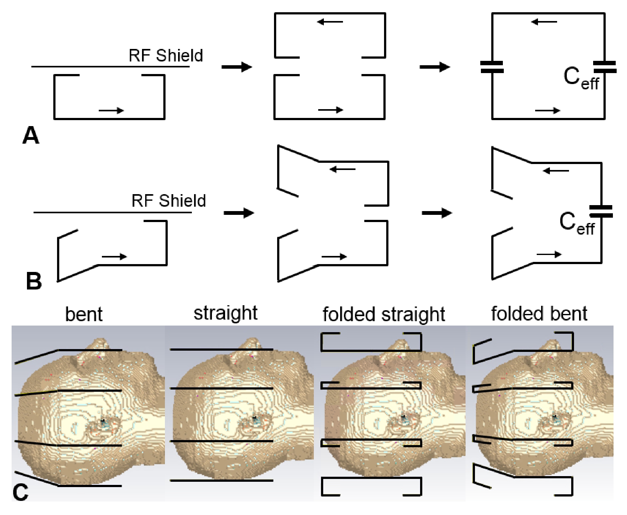
In comparison to surface loops, which are coupled inductively (positive reactance), a pair of loaded dipole antennas is coupled capacitively (negative reactance). Therefore, a mutual inductance has to be created to decouple dipole elements. Fig.1A demonstrates how this inductive coupling is produced by folding the dipoles and placing an RF shield near their folded portions. The presence of the shield is equivalent to placing a mirror image of the dipole carrying an opposite current at a distance double of the distance to the shield. Folded portions of both dipoles (a real dipole and its mirror image) produce a capacitive bridge, which depends on the distance to the shield and the folded length. Thus, by adjusting the distance to the shield and folded length, we can compensate the intrinsic capacitive coupling. In addition to folded straight dipoles (Fig.1A), we also evaluated other types of dipoles shown in Figs.1B and 1C. Electromagnetic (EM) simulations of the coupling between dipoles (S12), transmit B1+, and local specific absorption rate (SAR) were performed using CST Studio Suite 2017 (CST, Darmstadt, Germany) and the time-domain solver based on the finite-integration technique. Two voxel models were used, i.e. a head/shoulder (HS) phantom (ε = 58.6, σ = 0.64 S/m), and the virtual family multi-tissue model “Duke” (Fig.1C). All data were acquired on a Siemens Magnetom 9.4 T human imaging system. After numerical optimization of decoupling and evaluation of array performance and safety, we constructed and tested an 8-element single-row (1x8) array consisting of 30-mm folded bent dipoles (30 mm – the length of the folded portion).Results and Discussion:
As an example, Fig.2 shows the dependence of the S12 value on the length of the folded portion for different heights of the folded bent antennas and the size of the phantom. As seen from this figure, for each height of the dipole, a corresponding length can be chosen, which provides the lowest S12 value. It is noteworthy that creating capacitive coupling to the shield at one side of the dipole element (Fig.1B) is sufficient to generate a proper mutual inductance. Table 1 shows results of numerical evaluation of the average S12 value between adjacent dipoles for different 8-element dipole arrays. The 30-mm folded bent dipoles provide the best decoupling, which is about 7 dB better than that of unfolded dipoles. Figs.3A and 3B show a photo of the dipole array and the schematic of a single dipole element. Fig.3C shows S12 matrices measured using the new array for different heads. Average S12 value between all adjacent elements measured -16.6 dB and -18.4 dB for the smaller and larger head, respectively The constructed array delivers good decoupling even for a small head. As an example, Fig.4 shows a set of sagittal MP2RAGE images obtained using the dipole array.Conclusion:
We developed a novel method of decoupling of adjacent dipole antennas, and used this technique while constructing a 9.4 T human head 8-elelment TxRx dipole array coil. The array demonstrates good decoupling and full-brain coverage.Acknowledgements
SG acknowledges a support by Government of Russian Federation (Grant 08-08) and Ministry of Education and Science of the Russian Federation (No. 3.2465.2017/4.6). Funding by the European Union (ERC Starting Grant, SYNAPLAST MR, Grant Number: 679927) is gratefully acknowledged by AN and RL.References
1) Raaijmakers AJE, Ipek O, Klomp DWJ et al. Magn Reson Med 2011;66:1488-1497. 2) Oezerdem C., Winter L., Graessl A. et al. Magn Reson Med 2016;75:2553–2565. 3) Raaijmakers AJE, Italiaander M, Voogt IJ et al. Magn Reson Med 2016;75:1366–1374. 4) Clément J, Gruetter R, and Ipek Ö. Magn Reson Med 2019;81:1447–1458. 5) Connell IRO, Mennon RS IEEE Trans Med Imag 2019;38: 2177-2187. 6) Avdievich NI. Appl Magn Res 2011;41(2):483-506. 7) Jevtic J. Proc. ISMRM 2001, p. 17. 8) Shajan G, Kozlov M, Hoffmann J et al. Magn Reson Med 2014;71:870–879. 9) Avdievich NI, Pan JW, and Hetherington HP NMR in Biomed 2013;26(11):1547-1554.Figures
Figure
1.
Schematic representation of the decoupling effect caused by folding the dipoles
and placing the RF shield closely to the folded portion. The effect is demonstrated
for the folded straight dipoles (A) and folded bent dipoles (B). C) EM
simulation models of four different 8-element dipole arrays including the bent
dipole array, straight dipole array, folded straight dipole array, and folded bent
dipole array.
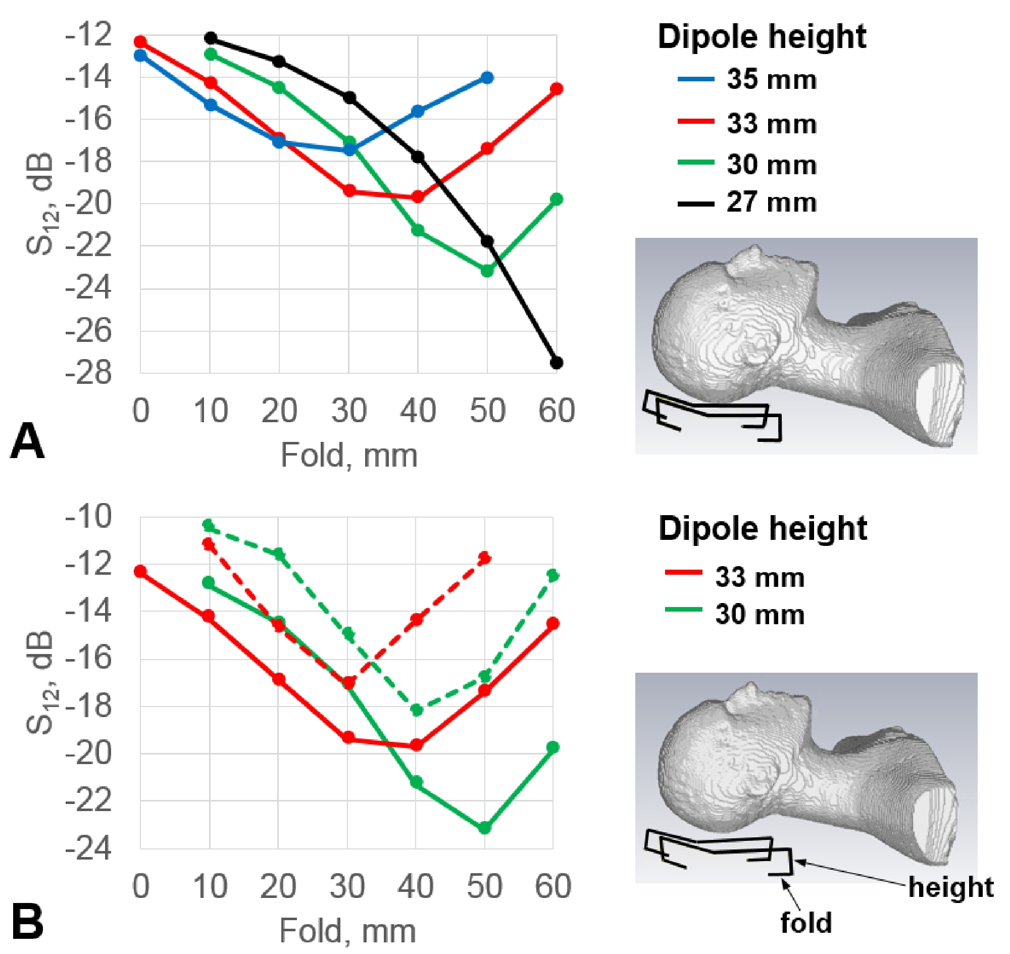
Figure 2. A) Dependencies of the S12 value on the length of the folded portion. S12
is measured between
a pair of folded bent dipole antennas loaded by the HS phantom for four different heights of the dipole. B) Similar as in
(A) dependencies acquired for two heights of the folded bent dipole and two
different in size HS phantoms. The smaller HS phantom is obtained by scaling
the original HS phantom by a factor of 0.9. Dashed lines correspond to the
smaller HS phantom. Both solid lines in Fig. 2B are shown for better comparison
and are the same as in Fig. 2A.
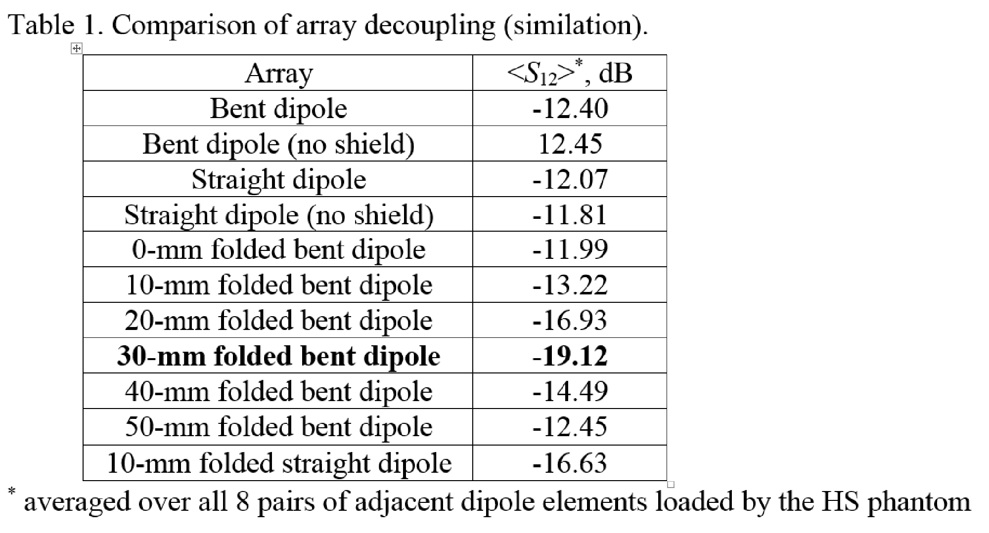
Table 1. Comparison of array
decoupling (simulation).
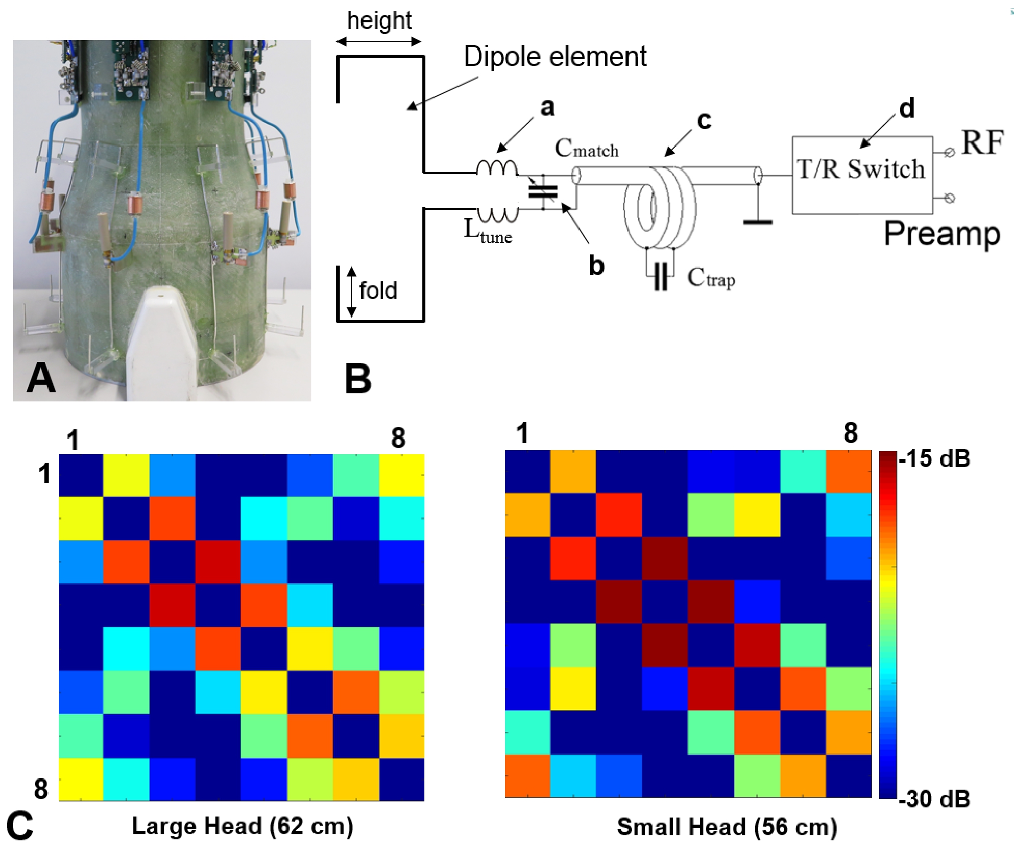
Figure 3. A) Photo
of the 30-mm folded bent dipole array with the cover and RF shield removed for
better visualization. B) Schematic of a single dipole element
including tuning inductors (a), matching capacitor (b), the cable trap (c), and
the T/R switch unit (d). C) S12
8x8 matrices experimentally measured using the 30-mm folded bent dipole array
for two subject with heads of different sizes, i.e. 62 cm and 56 cm in
circumference.
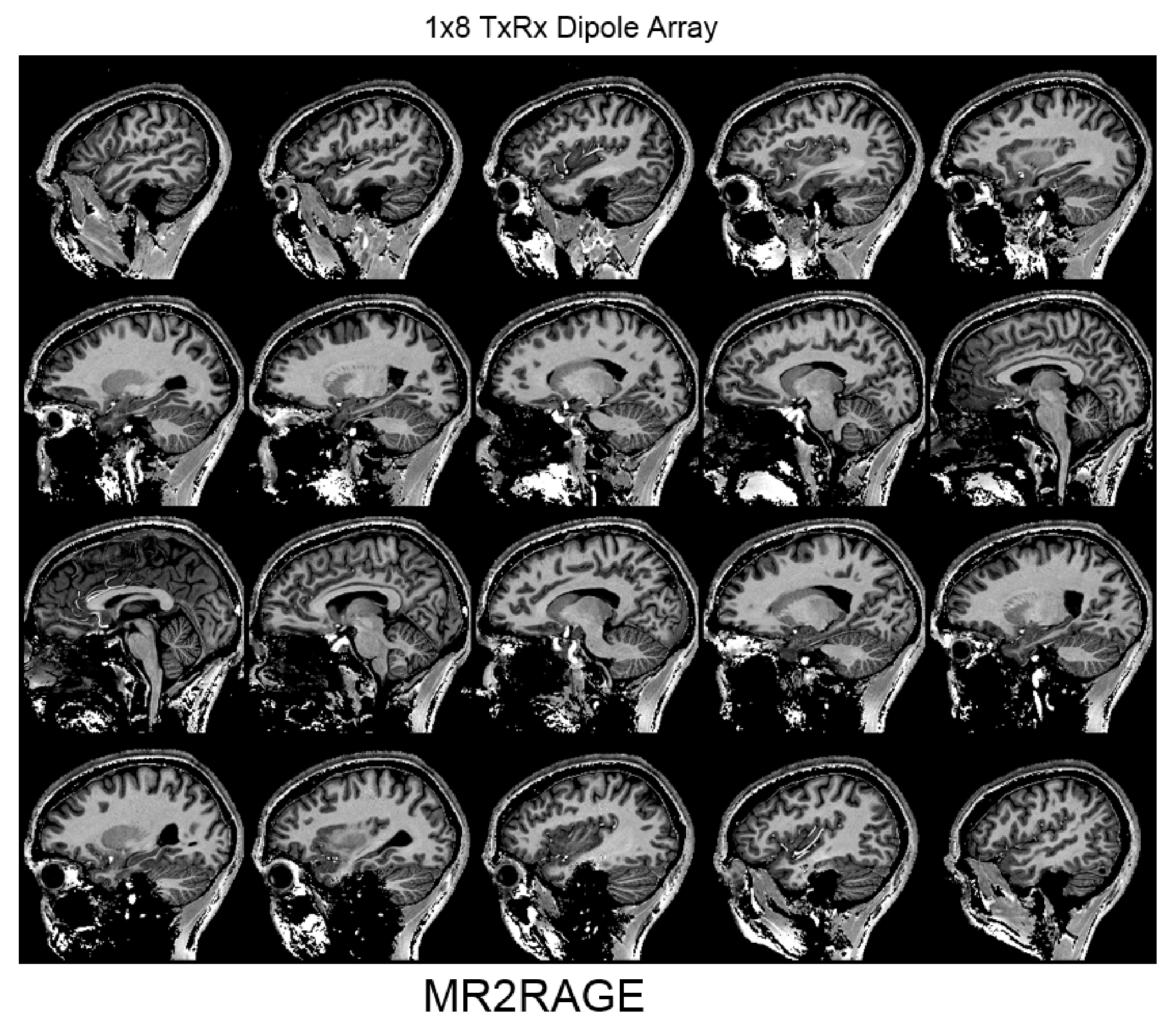
Figure 4. Sagittal in-vivo 1-mm isotropic whole-brain MP2RAGE
images obtained using the 8-element 1x8 30-mm bent folded
dipole array.